
3 Axis CNC Basic Guide
This guide explains the fundamentals of 3 axis CNC machining: how the three linear axes move, how a CAM file becomes G code, and how workholding decides what a part can hold. It is written for design engineers and buyers who need to judge whether a part should be cut on a 3-axis mill or pushed to 4 and 5 axes.
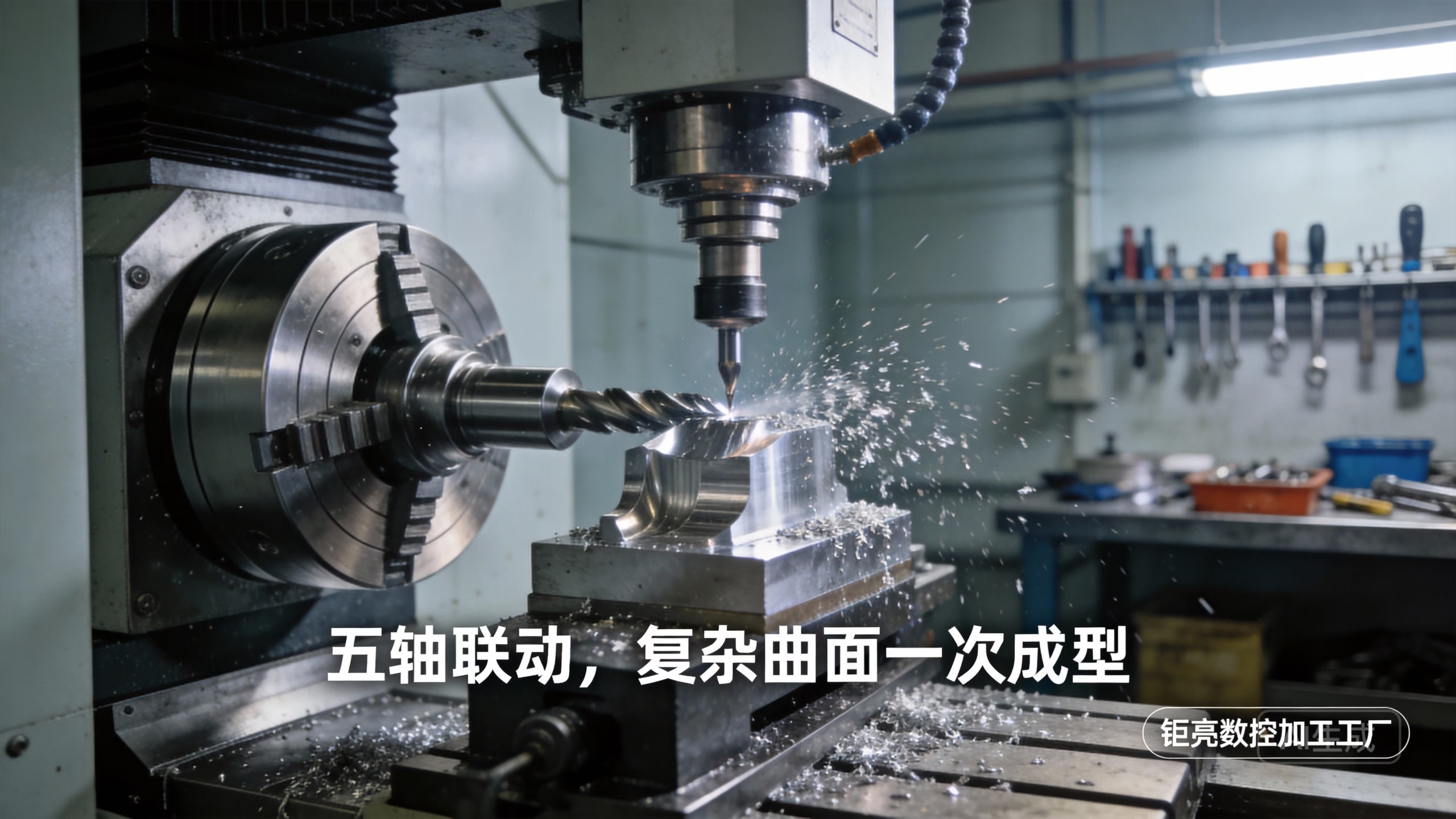
What the three axes actually do
A 3 axis CNC machine moves the cutting tool against the workpiece along three linear directions. X is left to right, Y is front to back, Z is up and down. The spindle turns the tool, the table or the column moves the part, and the controller keeps the two in step. That is the whole idea. No rotary table, no tilting head.
Because every cut comes from one tool orientation, the machined geometry has to be reachable from that direction. A pocket, a slot, a face, a step, a hole pattern on one side of the part: all of these are natural work for a 3-axis mill. The tool can only enter from above or, with a longer tool and a different setup, from a side. It cannot swing around a corner and cut a re-entrant feature in a single pass.
That limit is not a weakness. It is a trade. A 3-axis setup is cheaper to program, faster to prove out and simpler to inspect. For the majority of prismatic parts, the part is done in two or three setups and nobody needs a fourth axis.
- 1X axisLongest table travel, usually left to right.
- 2Y axisCross travel, front to back.
- 3Z axisVertical travel, controls depth of cut.
- 4One orientationTool axis stays fixed during the cut.
From CAD model to G code
The CAM programmer takes the solid model, defines stock, picks a coordinate origin, and chooses tools. The software then writes toolpaths: a series of linear and arc moves with a feed rate and a spindle speed for each. Those moves are post-processed into G code, the language the controller reads. M codes handle the auxiliary actions such as coolant on, spindle start, and tool change.
The toolpath is not the same as the finished surface. A ball nose tool leaves scallops between passes, and the stepover distance decides how tall they are. A flat end mill leaves a sharp corner at the bottom of a pocket that a smaller corner radius tool, or a separate operation, has to clean up. Engineers who read a CAM simulation before approving a design catch most of these problems early.
Feed and speed come from the material, the tool diameter, the number of flutes, and the rigidity of the setup. Aluminium 6061 runs fast with high rake angles and generous coolant. Inconel and hardened tool steel run slow, with coated carbide and a rigid holder. On a 3-axis machine, the weak point is often the part holding, not the spindle.
- 1RoughingRemoves bulk stock, leaves an allowance for finishing.
- 2FinishingSmall stepover, sets the final Ra value.
- 3Corner radiusMatch tool radius to pocket corners to avoid a second pass.
- 4SimulationCheck for gouges, collisions and thin walls before cutting.
Typical 3-axis capability at GreatLight
Numbers apply to the 3-axis group of 27 machines. Actual values depend on geometry, material and setup.
| Item | Value | Notes |
|---|---|---|
| Machines | 27 three-axis machines | Part of 127 CNC machines total |
| Tolerance | ±0.005 mm | ±0.0002 in |
| As-machined finish | Ra 1.6–3.2 μm | Standard milling |
| Fine finish | Ra 0.2–0.8 μm | After finishing passes |
| Compact travel | 500 × 500 × 450 mm | Also 500 × 310 × 200 mm |
| Medium travel | 750 × 1,150 × 550 mm | Also 600 × 600 × 600 mm |
| Large travel | 4,000 × 400 × 150 mm | Long prismatic parts |
| Rotary table | Ø400 mm | For indexed work on some cells |
Workholding decides more than the machine
Two parts of the same geometry can behave very differently on the same mill. A block clamped in a vise is rigid. The same block held on four tall parallel bars is not, and the tool will chatter on the finishing pass. Chatter shows up as a wavy wall and a finish that measures worse than the drawing allows.
For thin plates, the usual answer is to leave a thick web and cut it away in a second operation, or to hold the part on a sacrificial fixture with support underneath the cut. For long parts, more clamps along the length reduce lift. For parts with a tight flatness callout, rough machine first, release the stress, then finish cut after a short rest.
Number of setups matters for cost. Every additional setup adds a re-clamp, a re-datum and a chance for stack-up error. A 3-axis part that needs four sides machined normally means four setups, or a tombstone fixture that presents three faces at once. Designers who keep features on two or three faces usually get a cheaper part.
- 1ViseFast, rigid, good for small blocks.
- 2Soft jawsMachined to the part profile, protects finished faces.
- 3Vacuum plateGood for thin flat plates, low side load.
- 4TombstonePresents several faces in one setup.
When 3-axis is the right call, and when it is not
Choose 3-axis when the part is prismatic, when most features open to one direction, and when the tolerance is normal for milling. Brackets, housings, manifolds, base plates, heat sinks, jigs and fixtures all fall in this group. Prototypes and low-volume runs also fit well, because programming time is short and the first part comes off the machine quickly.
Move to 4-axis when the part is long and needs features on several sides at indexed angles, or when a cylindrical feature has to be milled with the part rotating. Move to 5-axis when surfaces are free-form, when the tool has to reach under a lip, or when one setup would replace four. Impellers, turbine blades, some medical implants and complex aerospace housings are 5-axis work.
The cost difference is real. A 5-axis program takes longer to write, the machine rate is higher, and the setup needs more care. Putting a simple bracket on a 5-axis center does not make it better; it makes it more expensive. A useful rule: if a 3-axis part can be finished in three setups or fewer and every feature is reachable from the tool axis, stay with 3-axis.
- 1Use 3-axisPrismatic parts, features on 2–3 faces, tight but simple tolerances.
- 2Use 4-axisIndexed features around a part, cylindrical milling.
- 3Use 5-axisFree-form surfaces, undercuts, one-setup consolidation.
- 4Watch costExtra axes raise programming and machine time.
3-axis material behavior at a glance
Practical notes for the materials we run most often on 3-axis mills.
| Material group | Examples | Typical behavior |
|---|---|---|
| Aluminium | 6061-T6, 7075, 6082 | Fast cutting, good finish, watch thin walls |
| Stainless | 303, 304, 316L, 17-4PH | Work hardens, needs sharp tool and steady feed |
| Carbon steel | 1018, 1045, 4140 | Predictable, rough then finish |
| Tool steel | Hardened grades | Slow speeds, rigid setup, coated carbide |
| Titanium | TC4 (Ti-6Al-4V) | Low thermal conductivity, heat at the edge |
| Copper and brass | C36000, C110 | Free cutting, gummy at low feed |
| Plastics | POM, PEEK, ABS, HDPE | Sharp tools, air blast, control chips |
How to check that a 3-axis part is correct
A finished 3-axis part is usually checked against the drawing on a coordinate measuring machine, with calipers and micrometers for simple features. The critical items are the datums, the position of hole patterns, wall thickness and the surface finish. Flatness and parallelism are the two calls that most often fail on thin parts.
In-process checks catch drift before the run is finished. A first-article inspection confirms the setup, then spot checks follow at intervals. If a tool wears, the hole diameter creeps and the operator compensates. Reports can be supplied when the drawing or the quality plan asks for them.
GreatLight inspects 100% of parts before shipment, with raw material verification, in-process monitoring and a final inspection step. The plants hold ISO 9001:2015, IATF 16949:2016, ISO 13485:2016 and ISO 27001:2022. Uploads are treated as confidential, and an NDA is available on request.
- 1First articleConfirms setup and datums before the batch runs.
- 2In-processSpot checks catch tool wear and thermal drift.
- 3FinalFull dimensional check against the drawing.
- 4ReportsAvailable when the quality plan requires them.
Common questions about 3 axis CNC
Is a 3-axis machine accurate enough for tight tolerances?
Yes, for the right geometry. Our 3-axis group holds ±0.005 mm (±0.0002 in) on parts where the setup is rigid and the tool is short enough to avoid deflection.
Long tools, thin walls and deep pockets reduce the achievable tolerance regardless of the machine. If your part has tall thin features, tell us at quote stage so we can plan the setup.
How many setups will my part need?
Most prismatic parts take two or three setups: one for the top face, one for the bottom, and sometimes one for a side feature.
Features that open to a single direction can often be cut in one setup. Features on four or more faces usually add cost, and that is when a 4-axis or 5-axis process may be cheaper overall.
Can you machine a part with undercuts on a 3-axis mill?
Not in a single pass. An undercut is hidden from the tool axis, so the part has to be re-clamped and the feature reached from another direction.
If the undercut is deep or curved, a 5-axis center with a tilted tool may be the better route because it avoids extra setups and the stack-up error they bring.
What surface finish can 3-axis milling reach?
As-machined milling typically lands between Ra 1.6 and 3.2 μm. With a finer stepover and a dedicated finishing pass, we reach Ra 0.8–1.6 μm, and down to Ra 0.2–0.8 μm on suitable materials.
Finish depends on the material and the tool, not only the machine. Soft plastics and aluminium take a finer finish more easily than titanium or hardened steel.
Do you offer 3-axis machining for prototypes and small runs?
Yes. There is no minimum order quantity, so a single prototype and a 10,000-part run both go through the same process control.
Quotation and a free DFM analysis come back within 12 hours, and production can start within 24 hours. Standard parts ship in 3–5 days.
Which materials are available for 3-axis work?
Aluminium 6061, 7075, 6082 and others; stainless 303, 304, 316L and 17-4PH; carbon steels 1018, 1045 and 4140; titanium TC4; copper and brass grades; and plastics including POM, PEEK and ABS.
If your material is not on the list, send the specification. We will confirm whether it can be cut on a 3-axis machine or needs a different process.
Send us your drawing and get a straight answer
Upload your CAD files and we will tell you whether 3-axis is the right process, then quote it. Free DFM analysis within 12 hours.
12-hour quote100% inspectionNo minimum order









