
3 Axis CNC Machining Services
This page explains what a three-axis setup can and cannot do: which geometries suit it, where the tolerance and finish limits sit, and how to fixture parts so the second operation stays aligned. It is written for design engineers and buyers who need to pick a process, not a slogan.
What a three-axis setup actually does
Three linear axes, one spindle orientation, and a part that has to be reached from the top, the side, or two setups.
How the axes move, and what that constrains
On a three-axis mill the cutter travels in X, Y and Z while the spindle stays vertical. The tool reaches any point inside the work envelope, but every cut is normal to the spindle axis. Undercuts, deep side pockets and features on the back face need a second setup, a fixture that tilts the part, or a different machine.
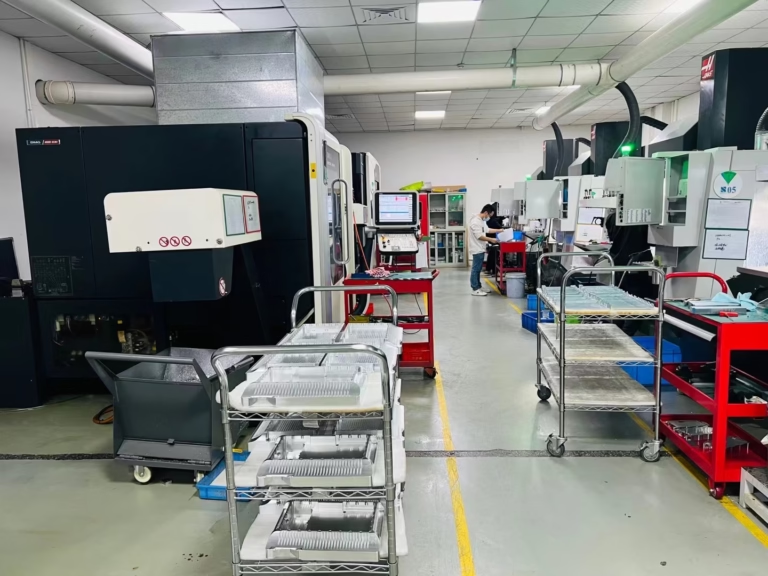
Three-axis work is the base of most machining shops, ours included. We run 27 three-axis machines alongside 12 four-axis mills and 16 simultaneous 5-axis centers. The three-axis group handles flat plates, brackets, housings, manifolds, jigs and any prismatic part whose features lie on accessible faces.
A three-axis setup is the fastest to program and the easiest to inspect. Tool paths are simple. Setup is repeatable. When a part fits this envelope, choosing a 5-axis machine adds cost without adding much.
Which parts belong on a three-axis machine
Parts with planar faces, through holes, counterbores, tapped holes, slots and pockets all sit comfortably on three axes. So do parts with loose tolerances on the back side, or parts you can flip once with a simple vise stop.
The decision usually turns on two questions. How many distinct faces carry features, and how tight must those features stay to each other? If the answer is one or two faces, and the cross-face tolerance is looser than ±0.02 mm, three-axis is the economical choice. If four or more faces carry tight features, repositioning error starts to dominate.
Deep cavities with a small corner radius are a poor match. A short three-axis tool cannot reach the bottom without a long, thin end mill that deflects. That is a geometry problem, not a machine problem.
Thin walls below roughly 1 mm are also awkward. Clamping force, cutting force and springback all push the wall around. Here a fixture change, a gentler stepover, or a four-axis approach from the side usually works better.
Three-axis or more? A quick guide
Match the part to the axis count before you compare prices.
| Part feature | Three-axis fit | Notes |
|---|---|---|
| Flat plate, holes on one face | Good | Single setup, fastest cycle |
| Bracket, features on two faces | Good | Flip once with a fixed stop |
| Four-sided housing, tight bores | Marginal | Repositioning error stacks up |
| Curved or angled surfaces | Poor | Needs 4 or 5 axis |
| Undercuts and back-side pockets | Poor | Second setup or tilted fixture |
| Deep pocket, radius under 2 mm | Poor | Tool deflection limits reach |
| Wall thickness under 1 mm | Marginal | Fixture and stepover matter |
| Large frame, holes on edges only | Good | Fits 4,000 mm travel |
Tolerance, finish and materials we run
Our three-axis group holds ±0.005 mm (±0.0002 in) on critical dimensions under controlled conditions. That number assumes a rigid setup, a sharp tool and a stable material. Aluminum 6061 and 7075 hold it more easily than thin-wall Inconel.
As-machined finish lands around Ra 1.6–3.2 μm. With a finishing pass and the right insert, Ra 0.8–1.6 μm is routine. Below Ra 0.2 μm we move to a polishing or lapping operation rather than chasing it on the mill.
All the usual materials run on three axes: 6061 and 7075 aluminum, 303 and 316 stainless, 1018 and 4140 steel, C360 brass, POM and PEEK. Plastics cut fast but move with heat, so we keep coolant and feed under control to hold size.
Every part goes through 100% inspection before shipment, with raw material checks, in-process monitoring and a final report available on request.
Fixturing decides whether the second operation holds
The real risk in three-axis machining is the flip. Once the part leaves the vise, you have a new datum, a new clamp load and a fresh chance to lose alignment. A soft jaw cut to the part profile, a stop pin, or a dedicated plate with dowel pins fixes most of it.
For runs above a few dozen pieces we build a fixture that locates on a machined feature rather than on the raw stock. That single change often holds cross-face position to ±0.01 mm without touching the machine.
Where a part needs a third face machined and volume is low, a tilting vise or an angle plate beats a 5-axis quote. The setup takes longer, but the tool path stays simple and the inspection stays straightforward.
We can design and cut these fixtures in-house. Send the drawing and we will tell you where the setup risk sits before the job starts.
When to move to four or five axes
Move up when the part has features on four or more faces, when compound angles must be cut in one pass, or when a contoured surface needs to be followed with a short tool. Those cases spend more time in repositioning than in cutting on three axes.
A four-axis machine adds a rotary table, usually Ø400 mm on our floor. That lets the part index around a single axis, so a shaft with cross holes or a cylinder with radial slots is cut without a second setup. It is the cheapest step up from three axes.
Five-axis simultaneous motion suits impellers, medical implants and complex aerospace housings. We keep 16 such centers for that work. If your part is flat and prismatic, though, three-axis will quote lower and ship faster.
No minimum order quantity applies here. One prototype or a 10,000-piece run both run through the same inspection routine.
Questions engineers ask about three-axis work
Can a three-axis machine cut an angled face?
Yes, but not in one setup with a vertical spindle. The part is tilted in a fixture, or the operation moves to a four-axis machine with a rotary table.
For a single shallow angle on a low-volume part, a tilted fixture is usually cheaper than reprogramming.
What tolerance can we realistically expect?
±0.005 mm on critical dimensions with a rigid setup and a sharp tool. Looser faces commonly run at ±0.02 mm.
Thin walls and hard alloys push the achievable number outward. Tell us which dimensions matter and we will quote to those.
Do you charge for the fixture?
Soft jaws and simple stops are part of the setup. A dedicated plate with dowel pins is quoted separately when the run justifies it.
For one-off parts we usually work with standard vises and adjustable stops.
How tight can the surface finish get?
Ra 1.6–3.2 μm as machined, Ra 0.8–1.6 μm with a finishing pass. Below that we polish or lap the part.
Bead blasting and anodizing change the measured finish, so specify the finish after coating if it matters.
What file formats do you accept?
STEP and IGES for solid models, DXF for flat profiles, and PDF for drawing views with tolerances.
Uploads stay confidential and an NDA is available on request.
How fast can parts ship?
Quotation and a free DFM analysis come back within 12 hours. Production can start within 24 hours, and parts typically ship in 3–5 days.
Complex fixtures or outside finishing add time, and we will say so in the quote.
Send a drawing and get a three-axis quote
Upload your model and we will return a price, a DFM note and a setup plan within 12 hours.
12-hour quote100% inspectionNDA on request









