
3D Printer Suture Repair: Salvaging Metal AM Parts
This guide is for engineers and buyers who have a failed DMLS, SLM or EBM build on the bench and need to know whether it can be saved. We cover how to read the defect, which repair route fits which geometry, and when a repair costs more than a reprint. You will finish with a decision checklist you can apply to your own parts.
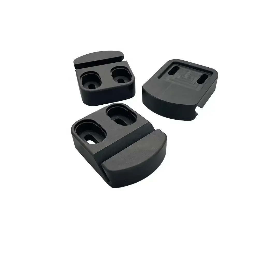
What 3D printer suture repair actually means
A stitch, not a restart: remove the failed zone, rebuild it, then bring the part back to drawing.
Why a metal build fails in the first place
Metal powder-bed printing melts or sinters layer by layer. Every layer is a small weld. When one layer does not bond properly, the error travels upward and shows up much later as a crack, a void or a rough patch. That is why a failure at layer 400 often looks like a failure at layer 1200.
The usual causes fall into four groups: powder problems, laser or beam problems, thermal stress, and geometry. Contaminated or reused powder changes the melt pool. A drifting focus lens or a worn recoater blade leaves a thin line of un-melted powder. Long thin sections cool fast and curl.
None of these are random. Each leaves a signature you can read on the part or in the build log. Reading that signature is the first step of any 3D printer suture repair, because the repair method has to match the defect type.
Skip the cause and you will stitch the same defect twice. A crack from thermal stress will reappear next to the weld if the surrounding metal is still brittle.
Reading the defect before you cut
Start with the build report, then move to the part. Layer number, position on the plate, and gas flow direction narrow the cause fast. A defect that repeats at the same height across several parts points to the machine, not the design.
On the part itself, look for three things. First, porosity: pin holes or a dull grey patch that does not take a polish. Second, lack of fusion: sharp-edged voids, often with un-melted powder inside. Third, cracking: long, straight, usually near a thick-to-thin transition.
Dye penetrant finds surface-breaking cracks that the eye misses. For internal voids, industrial CT is the only reliable method, but it costs money and time. Use it when the part is safety-critical or when a repair decision depends on void size.
Record what you find. Depth, length, location, and whether the defect crosses a functional surface. That record decides the repair route and tells you whether the part is worth saving.
Defect to repair route
Match the failure mode to the least risky fix.
| Defect | Typical location | Best repair route | Reprint when |
|---|---|---|---|
| Surface porosity | Skin, non-critical face | Weld build-up, then re-machine | Porosity covers the whole face |
| Lack of fusion | Internal, near support side | Cut out, re-weld, CT check | Void sits in a load path |
| Thermal crack | Thick-to-thin transition | Groove out, weld, stress relieve | Crack exceeds 10 mm depth |
| Warp / curl | Thin walls, overhangs | Re-machine to drawing | Stock is under the min wall |
| Dimensional drift | Bores, sealing faces | CNC re-cut with new datums | No stock left on the feature |
| Support damage | Downskin surfaces | Blend and polish | Downskin is a sealing face |
How a suture repair is carried out
Step one is removal. The bad metal has to go completely, not just be covered. We machine or grind a groove until the cut reaches sound material on all sides. A dye check confirms the boundary before any weld goes in.
Step two is rebuilding. For most nickel and titanium alloys, TIG or laser welding with matching filler restores the volume. Preheat and interpass temperature matter more than the weld itself on crack-prone alloys. On small features, laser cladding gives a tighter heat-affected zone.
Step three is bringing the part back to drawing. Welded metal is never in the right place. We re-datum the part off untouched surfaces and CNC machine the repaired zone to the original tolerance. This is where a repair shop needs both AM and machining capability.
Step four is verification. Dimensional inspection, dye penetrant, and on request CT or X-ray. A repaired part gets the same inspection route as a new one. Anything less is guesswork.
- 1Remove to sound metalGroove out until dye check shows no indication at the boundary.
- 2Match the fillerSame alloy family as the base; never mix titanium and nickel fillers.
- 3Control heatPreheat and interpass limits stop a new crack forming beside the weld.
- 4Re-machine after weldingNew datums off untouched faces keep the repaired zone in tolerance.
What you can hold after a repair
A repaired zone is never as clean as virgin material. The heat-affected zone has a different grain structure, and the filler may not match the base alloy exactly. That limits what the part can be used for.
For non-critical brackets and housings, a repair is usually fine. The part holds ±0.005 mm on re-machined features and passes a dye check. For rotating parts, pressure boundaries, or anything in a fatigue cycle, treat a repair as a temporary fix at best.
Surface finish is the other limit. Welded areas polish to Ra 0.8–1.6 μm with work, but a mirror finish on a large repaired face is hard to guarantee. Plan for Ra 1.6–3.2 μm if the repair area is wide.
Tell us the service condition up front. Material, load direction, temperature, and whether the part is safety-critical. That decides whether we recommend a repair or a reprint, and we will say so before you spend money.
When to repair and when to reprint
Repair wins when the part is expensive, the lead time is long, or the geometry is hard to rebuild. A large titanium housing with 60 hours of print time and a single crack on a non-critical flange is a clear repair case.
Reprint wins when the defect is in a load path, when the part is small, or when the root cause is still unknown. Stitching a part that will fail again is worse than starting over.
Use a simple rule. If the defect touches a sealing face, a bearing bore, or a fatigue-critical section, reprint. If it sits in a non-functional boss or a cosmetic area, repair is worth costing out.
A repair quote should always come with a reprint quote beside it. Then the decision is a number, not a feeling.
Common questions
Can a cracked metal 3D printed part be welded?
Yes, for most aluminium, stainless, titanium and nickel alloys, provided the crack is grooved out to sound metal first.
Welding over a crack without removing it just hides the defect. The crack will reopen under load.
Does welding change the material properties?
It changes the local grain structure and leaves a heat-affected zone. Hardness and ductility near the weld will differ from the base metal.
For non-critical features that is acceptable. For fatigue or pressure applications, a repair is not equivalent to a new part.
How do you know the repair is sound?
Dye penetrant on the surface, dimensional inspection on re-machined features, and CT or X-ray for internal quality on request.
A repaired part goes through the same inspection route as a new one. Reports are available if you need them.
Can you re-machine an AM part without repairing it?
Yes. Warp, dimensional drift and rough downskin can often be fixed by re-cutting with new datums, as long as there is stock left on the feature.
Once the stock is gone, the only options are weld build-up or a reprint.
What information do you need for a repair assessment?
The alloy, the drawing or CAD with tolerances, the defect location and size, and how the part will be used.
A build report or photos help. Send them through the quote page and we return a DFM analysis within 12 hours.
Send us the failed part details
We will tell you whether a 3D printer suture repair is worth it, or whether a reprint is the cheaper route. No minimum order, from one part up.
12-hour quoteFree DFM analysis100% inspectionNDA on request









