
3D Printing Colorado: Top 7 Mistakes to Avoid in 2025
A process engineer's list of the seven errors that send additive parts back for rework. Written for design engineers and sourcing teams along the Front Range who need printed parts that survive testing and fit the assembly.
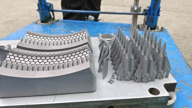
Where printed parts actually fail
Most additive failures trace back to a decision made before the first slice file.
Choosing the process before the function
The most common error is picking a printer technology before writing down what the part has to do. FDM, SLA, SLS, SLM and DMLS are not interchangeable. Each one carries its own layer thickness, anisotropy and material set, and those differences decide whether a bracket holds load or cracks at the third bolt hole.
Start with the load case. A concept fit-check that never sees stress is fine on FDM. A manifold that carries 200 bar, or a bracket that sees vibration on a drone airframe, is not. When a part touches a flight-critical or implant-critical assembly, the print process has to be qualified, not just available.
Cost and lead time follow the process choice, not the other way around. Teams that buy a desktop printer because it looks useful often end up reprinting the same bracket three times. A service bureau with a validated process costs more per part and less per project.
- 1Fit-check onlyFDM or SLA is enough; skip the qualification paperwork.
- 2Load-bearingPrint in metal or design for fiber orientation.
- 3Regulated assemblyRequire material certs and process records up front.
Skipping design for additive manufacturing
DfAM is not a cosmetic step. The layer-by-layer build direction sets the weak axis, and every surface that overhangs needs support that someone has to cut away later. A 45° rule of thumb for self-supporting walls saves hours of finishing and reduces the risk of a collapsed overhang.
Internal channels are where designs quietly die. A horizontal channel inside an SLM manifold needs dense internal support that cannot be reached with a tool. The part comes back blocked, and the scrap rate hits 100%. Angle internal passages so powder clears, and keep them round for flow.
Lattice and hollow sections cut weight and build time, but only when the cell size stays above the minimum feature the printer can hold. Below that, the lattice prints as a solid blob and you have paid for the weight you tried to remove.
- 1OrientationSet build direction before detailing features.
- 2OverhangsKeep unsupported angles under about 45°.
- 3Trapped powderAdd escape holes to every enclosed cavity.
Treating material data sheets as the whole story
A data sheet lists tensile strength for a bulk specimen. A printed part is not a bulk specimen. Interlayer adhesion, porosity and build orientation can pull real strength well below the published number, and that gap widens on thin walls and small cross-sections.
Certification matters as much as the number. Aerospace, medical and automotive programs need traceable material, lot control and documented process parameters. Ask for the material certificate and the heat lot before the build starts, not after the parts arrive at receiving inspection.
For metal parts, post-build heat treatment and HIP decide fatigue life. Printing to near-net shape and then machining the mating surfaces gives you the geometry of additive and the tolerance of subtractive work in one part.
- 1Directional strengthTest coupons in the same orientation as the part.
- 2TraceabilityRequire lot numbers and mill certs for metals.
- 3FatigueSpecify HIP plus heat treat for cyclic loads.
Over-engineering tolerance and finish
Print resolution and part tolerance are different things. Quoting ±0.05 mm on every dimension of an as-printed part drives cost up and often cannot be measured reliably on a curved surface. Reserve tight tolerances for the features that mate with something else.
Surface finish works the same way. A printed surface at Ra 12 μm is normal for an as-built SLM wall. If a sealing face needs Ra 0.8–1.6 μm, plan a machining pass on that face alone instead of trying to print it smooth.
Blanket tolerance callouts also slow inspection. A drawing with twelve tight dimensions needs twelve measurements per part. A drawing with three critical ones moves faster through first article and costs less to check.
- 1As-printedHold loose tolerances; add stock where it matters.
- 2Mating surfacesMachine after printing to ±0.005 mm.
- 3Sealing facesSpecify Ra 0.8–1.6 μm on the face only.
Leaving secondary operations out of the plan
Almost every functional printed part gets touched by a second process. Threads, bores, bearing seats and flat mounting faces usually end up on a mill or a lathe, because printed threads strip and printed bores do not hold a press fit.
Build the print with machining stock. Add 0.3–0.5 mm on faces that will be cut, and design a fixturing feature the machinist can clamp without crushing the part. A printed boss with a flat pad is easy to hold. A thin curved shell is not.
Finishing follows the same logic. Anodizing, bead blasting and laser marking change dimensions slightly, and masking a printed surface for selective anodizing takes time. Decide which surfaces stay raw before the parts leave the printer.
- 1ThreadsCut them after printing, not in the build.
- 2BoresLeave stock and ream to final size.
- 3MaskingMark surfaces that stay unfinished on the drawing.
Cost, lead time and the build volume reality check
Complex builds cost more than the quote suggests when support removal, heat treat and machining are billed separately. Ask for a line-item price that includes post-processing, or the invoice will surprise you. Metal powder is priced by weight and by alloy, and a titanium build costs several times the same volume in aluminum.
Lead time behaves the same way. Printing time is only part of the schedule; heat treat, HIP and machining add days that a print-time estimate ignores. A realistic plan for a metal part with machined interfaces runs from a week to several weeks depending on alloy and finishing.
Build volume is the last trap. A part that fits the envelope may still need to be split, and that split introduces a joint that has to be aligned and often welded. Check the diagonal, not just the bounding box, and check whether the orientation that fits is also the orientation that holds load.
- 1Quote line itemsAsk for post-processing as separate lines.
- 2ScheduleAdd heat treat and machining days to print time.
- 3EnvelopeVerify part diagonal against the build chamber.
Matching the process to the part
Use this as a first pass, then confirm with a DfAM review.
| Part requirement | Print process | Follow-up operation |
|---|---|---|
| Concept fit-check, no load | FDM | Deburr, sand if handled |
| Visual model, smooth skin | SLA | Prime and paint |
| Ducting, non-critical brackets | SLS | Bead blast, dye |
| Load-bearing metal bracket | SLM or DMLS | Heat treat, machine faces |
| Sealing face or bearing bore | Any metal AM | CNC to ±0.005 mm |
| Threaded holes | Metal AM or FDM | Tap or thread mill after print |
| Large panel over 1 m | Split build or sheet metal | Weld, align, machine |
| Regulated implant or flight part | Qualified DMLS | HIP, heat treat, full inspection |
Questions engineers ask before the build
Can a printed part hold a press-fit bearing?
Print the bore undersize with 0.3–0.5 mm of stock, then ream or bore it on a CNC to the final diameter and tolerance. As-printed bores vary by layer and orientation, so a press fit straight off the printer is a gamble.
If the bore is a critical interface on a metal part, machine it after heat treat so the geometry stays stable.
How much does build orientation change strength?
It can change tensile behavior noticeably along the layer direction compared with the in-plane direction. For parts under load, set the build so the primary stress runs in-plane, not across layers.
When the load path is unclear, print test coupons in the same orientation as the production part and pull them before committing to a run.
When should we print and when should we machine from solid?
Print when the geometry has internal channels, lattices or organic shapes that a cutter cannot reach. Machine from solid when the part is mostly prismatic and needs tight tolerances on several faces.
A hybrid route works well: print near-net for the complex features, then machine the mating surfaces to ±0.005 mm.
What do you need for a DfAM review?
Send the 3D model, the material and any load or temperature requirements, plus the surfaces that mate with other parts. We return a quotation and free DFM analysis within 12 hours.
Uploads stay confidential, and an NDA is available on request before you send files.
Does post-processing add real lead time?
Yes. Heat treat, HIP, bead blasting and machining each add their own queue time. A metal part with machined interfaces needs more calendar days than the print alone suggests.
Plan the operations as one sequence and confirm the schedule with the shop rather than estimating from print hours.
Can you handle both the printing and the machining?
We run custom 3D printing alongside 127 high-precision CNC machines, including 16 simultaneous 5-axis machining centers with a maximum processing size of 4,000 mm. That lets one supplier own the print, the post-processing and the final inspection.
Every part is inspected before shipment, with reports available on request.
Send the model, get a manufacturable answer
Quotation and free DFM analysis within 12 hours, from a single prototype to 10,000+ part runs.
12-hour quote±0.005 mm machiningISO 9001 / IATF 16949NDA on request









