
3D Printing Healthcare News: 5 Life-Saving Breakthroughs
A look at five medical parts that moved from a 3D print to a working device: patient-matched implants, surgical instruments, cranial shunts, alignment guides, and drug-delivery hardware. For engineers and buyers deciding where additive stops and machining starts. You will finish with a clear read on which process fits which part.
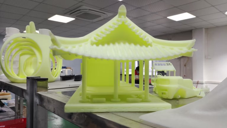
The gap between a print and a device
Additive gives you the shape. Something else has to give you the fit, the thread, and the surface.
Patient-matched implants and the machined interface
Most 3D printing healthcare news lands on the printed body of an implant. The acetabular cup with a porous lattice. The cranial plate that follows a CT scan. What the coverage skips is the interface. A printed titanium lattice will not hold a locking screw on its own. Screw holes, taper seats, and mating faces are cut after printing, usually on a 5-axis mill.
The reason is tolerance stacking. A print might land within ±0.2 mm on a curved surface, which is fine for bone contact. It is not fine for a Morse taper that must seat at a fixed angle, or a threaded hole that takes an M3 locking screw. If you print the thread and never cut it, the surgeon feels the wobble in the tray.
We see this on femoral knee components, spinal interbody fusion cages, and custom titanium orthopedic plates. Ti-6Al-4V prints well and machines well, but the two processes want different things. Printing likes thin walls and lattice. Machining likes a solid boss to hold a thread. The design has to serve both.
A workable sequence: print the blank with stock on every critical face, anneal, then cut datum faces, bores, threads, and taper seats in one 5-axis setup. That keeps the number of re-fixturings low and the positional tolerance tight. It also removes the support-removal marks that would otherwise sit on a wear surface.
- 1Print, then cutReserve 0.3–0.5 mm stock on tapers, bores, and threads.
- 2One setup for critical facesDatum, bore, and thread in the same 5-axis cycle.
- 3Skip printed threadsCut them. Printed threads rarely hold torque repeatably.
- 4Support removal mattersKeep support marks off wear and sealing surfaces.
Surgical robotics and micro-instrumentation
Robotic surgery pushed instrument shafts toward 3–5 mm outside diameter with internal channels for actuation cables and flushing. Printing gets you a channel that curves. It does not get you a 0.5 mm wall on a 300 mm shaft that stays straight under load. That part is usually turned, gun-drilled, or milled from 17-4PH or 316L.
The useful split is blunt and simple. Printed handles and brackets, if the load is low. Machined shafts, clevis ends, and wrist joints, because those carry the tolerance and the fatigue load. A printed clevis pin hole will ovalize. A reamed 4H7 hole will not.
Micro-instrumentation raises a second issue: burrs. A burr inside a 1.2 mm flush channel is a patient risk, not just a cosmetic defect. We deburr with controlled abrasive flow and inspect under magnification. For some parts, electropolishing after machining removes the last of the edge without changing the geometry.
Instrument sets also get reprocessed. Steam autoclave cycles, enzymatic cleaners, and repeated handling wear a surface. Anodized aluminum handles can pit over time. Passivated 316L and 17-4PH hold up better. When a design mixes printed polymer grips with a machined stainless frame, the two materials age at different rates and the joint loosens.
- 1PrintedHandles, brackets, low-load housings, complex internal routing.
- 2MachinedShafts, clevis ends, wrist joints, sealing faces, threads.
- 3DeburringControlled abrasive flow plus visual inspection under magnification.
CSF shunts and the valve body problem
Cerebral spinal fluid shunts are small, low-flow devices. A valve body has a seat, a diaphragm, and ports that must not leak at pressures measured in centimeters of water. Printing a one-piece valve body looks elegant until you need a lapped seat and a flat cover face. Those are machined.
The pressure side of a shunt needs a surface finish that a print cannot reach as-printed. A lapped or fine-milled seat at Ra 0.2–0.8 μm gives the diaphragm something to seal against. We machine those seats in PEEK or titanium, depending on the implant duration and the imaging requirements.
Shunt hardware also has to survive MRI. That pushes material choice toward titanium, PEEK, and non-ferrous alloys, and it rules out any stray magnetic stainless in the assembly. If a printed housing carries a magnet for a programmable valve, that magnet sits in a machined pocket with a defined depth, not a printed cavity.
Catheter connectors are another spot where printing and machining meet. The barb and the luer taper are toleranced features. Cut them. The printed body around them can carry the grip geometry and the strain relief.
- 1Lapped seatRa 0.2–0.8 μm on the diaphragm contact face.
- 2MRI-safe stackTitanium, PEEK, and non-ferrous alloys; no stray magnetic steel.
- 3Tapered fittingsLuer tapers and barbs are cut, not printed.
Alignment guides, models, and drug-delivery hardware
Two more breakthroughs show up in the same news cycle: printed surgical guides and printed anatomical models for pre-op planning. Both are low-load, and both benefit from additive. A drill guide, though, has a metal sleeve in it. The sleeve bore is reamed to fit, and the guide body is often machined or printed and then bored to suit.
Drug-delivery hardware is the harder case. Pump manifolds, microfluidic channels, and needle hubs combine fine internal geometry with sealing faces. Printing gives the channel. Machining gives the seal land, the thread, and the luer. On a single part, that means printing a near-net blank with stock on the sealing faces and then finishing on a mill-turn center.
We keep a simple test for whether a printed feature needs machining. Ask what the feature does. If it guides flow, carries a cable, or fills space, print it. If it seals, threads, locates, or wears, cut it. That one question resolves most of the arguments in a design review.
There is a cost angle too. Printing a part and then machining it adds a setup and a stock allowance. It is worth it when the printed geometry would be expensive to machine, like internal lattice or a curved channel. It is not worth it when the part is basically prismatic. For that part, just machine it.
- 1Print itFlow channels, cable routing, space-filling geometry, lattice.
- 2Cut itSeals, threads, locating bores, wear faces, tapers.
- 3Near-net blankAdd stock on sealing faces, then finish on a mill-turn center.
Which process for which medical feature
A quick reference for the parts that show up in this news cycle.
| Feature | Process | Typical material | Why |
|---|---|---|---|
| Porous bone-contact lattice | 3D print | Ti-6Al-4V | Only additive builds open porosity |
| Morse taper seat | 5-axis mill | Ti-6Al-4V, 316L | Angle and contact area must hold |
| M3 locking screw hole | Mill or tap | Ti-6Al-4V | Printed threads lose torque |
| Instrument shaft, 3 mm OD | Turn or gun-drill | 17-4PH, 316L | Straightness and wall control |
| Valve seat, low flow | Fine mill or lap | PEEK, titanium | Ra 0.2–0.8 μm for sealing |
| Anatomical planning model | 3D print | Resin, PA | Shape only, no load |
| Luer taper and barb | Turn | PC, PEEK, 316L | Toleranced fit to mating part |
| MRI-safe magnet pocket | Mill | PEEK, titanium | Defined depth, no magnetic steel |
What to check before you release a hybrid part
A part that is printed and then machined has two process histories. The inspection plan has to cover both. We check the incoming print for density and critical dimensions, cut the datums, then monitor the machined features in process and do a final inspection before shipment. Reports are available on request.
Material traceability is the other half. A Ti-6Al-4V print and a Ti-6Al-4V bar can carry different certifications and different heat-treat states. If the implant relies on the annealed condition for fatigue, the print and the bar need to match. We ask for the powder certificate and the bar certificate and keep both with the job.
For medical programs, the quality system matters as much as the tolerance. Our plants hold ISO 9001:2015, IATF 16949:2016, ISO 13485:2016, and ISO 27001:2022. The 13485 scope is the one medical device buyers usually ask about. It covers the process control and record-keeping around the part, not just the measurement.
One more practical point. Cleaning. A printed lattice traps powder and support debris. A machined surface traps chips and cutting fluid. Both need a validated cleaning step before the part goes into a sterile barrier. We plan that step with the customer rather than assuming a rinse is enough.
- 1Two process historiesInspect the print and the machined features separately.
- 2Match the heat-treat statePowder and bar certificates travel with the job.
- 3Plan the cleaning stepLattice debris and machining chips need different removal.
Questions engineers ask next
Can you machine a 3D-printed medical part without distortion?
Yes, if the print is stress-relieved before cutting and the stock allowance is even on all machined faces. Uneven stock pulls the part as material is removed.
We usually ask for 0.3–0.5 mm on tapers, bores, and sealing faces, and we take light finishing passes on thin-walled sections.
Which materials do you machine for medical devices?
Titanium TA1, TA2, and TC4 (Ti-6Al-4V); stainless 316L, 17-4PH (SUS630), 303, and 440C; PEEK, PC, and PMMA for non-implant hardware.
We also machine aluminum 6061-T6 and 7075 for instrument housings and test fixtures.
What tolerance and finish can you hold on these features?
Down to ±0.005 mm on critical features, with finishes from Ra 0.2–0.8 μm on sealing and wear faces.
As-machined surfaces sit around Ra 1.6–3.2 μm where the drawing does not call out a finer finish.
Do you sign an NDA for medical device work?
Yes. Uploads stay confidential and an NDA is available on request before you send drawings.
We can also work from a marked-up drawing if you prefer not to release the full CAD model at the quote stage.
How do you handle small quantities and prototypes?
There is no minimum order quantity. We run from one prototype to 10,000+ part runs on the same process plan.
A quotation and free DFM analysis come back within 12 hours, and production can start within 24 hours.
Can you finish and mark the parts as well?
Yes. Anodizing, electroless nickel, passivation, bead blasting, polishing, and laser marking are done in house.
Laser marking has a minimum character height of 1.5 mm, which matters on small instrument shafts.
Send the print, get a machining plan
Upload your model and we will flag which features to cut, which to print, and what stock to leave. Quotation and DFM analysis within 12 hours.
12-hour quote100% inspectionISO 13485:2016No MOQ









