
3D Printing PEEK Composite: Process, Fillers and Machining Limits
A working guide for engineers who need high-temperature, chemically resistant parts. We cover what 3D printing PEEK composite can hold, which fibre or filler fits which load case, and where the printed part stops being the right answer. By the end you can pick between printing and CNC machining a PEEK component without guesswork.
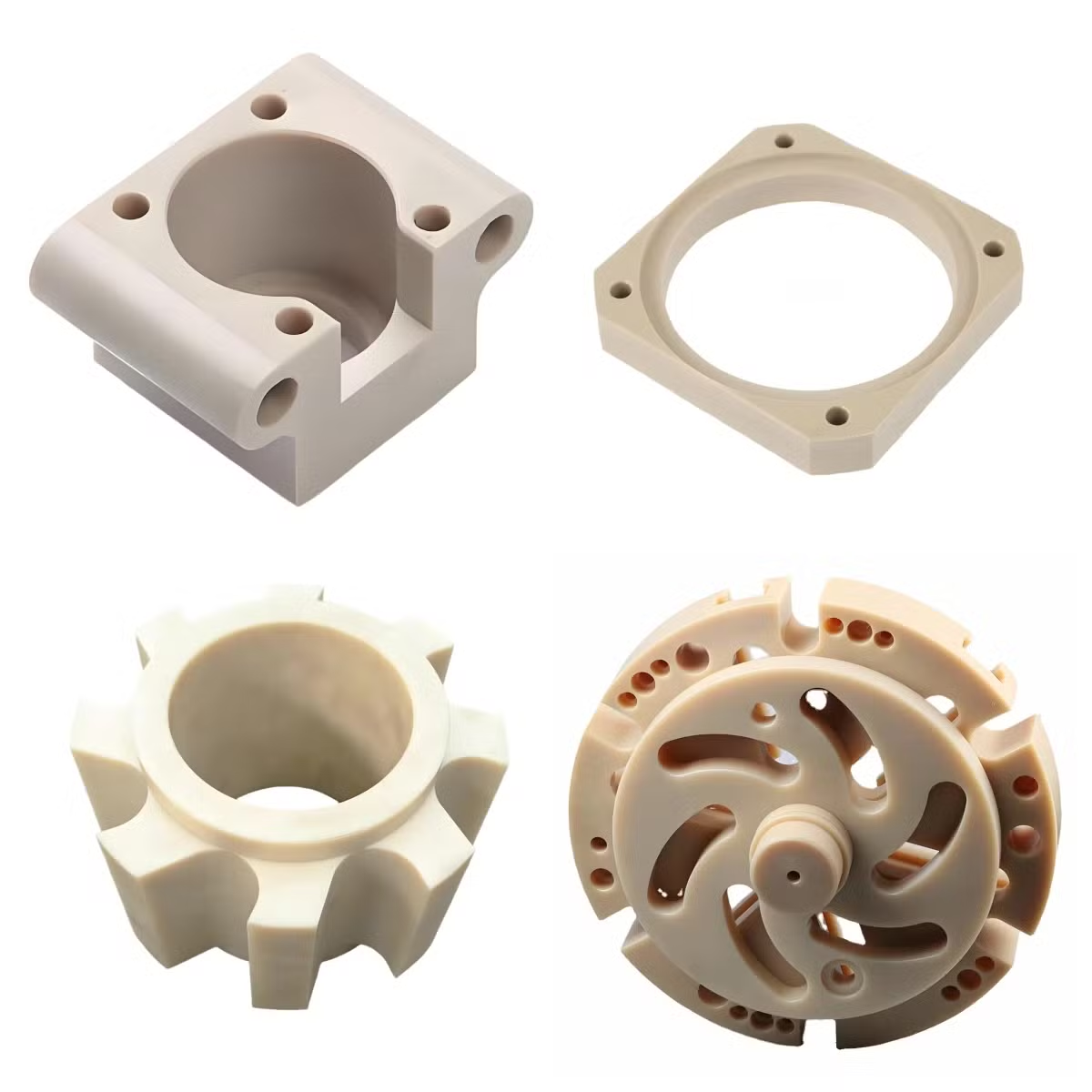
What this page covers
PEEK is a semi-crystalline aromatic polymer. Printing it with a fibre or mineral filler changes the melt, the shrinkage and the mechanical numbers you can rely on.
Why PEEK gets printed at all
Polyetheretherketone is a high-temperature engineering thermoplastic. Unfilled PEEK keeps useful stiffness up to roughly 250 °C continuous, resists most solvents and fuels, and is radiolucent, so it does not throw artefacts on X-ray or CT. It also has a low wear rate against metal and decent biocompatibility. That combination is why it shows up in dental and oral devices, sterilizable fixtures, and aircraft brackets where metal would be too heavy or too radio-dense.
The catch is that PEEK is expensive and hard to machine into thin, organic shapes. Printing lets you build a lattice, a hollow shell or a patient-specific contour without paying for a five-axis setup and half a block of stock turned into chips.
Standard FDM or FFF printers will not touch it. PEEK needs nozzle temperatures from 360–450 °C and a chamber held above 150 °C, ideally 200 °C and up. Below that, the bead cools too fast, the layers do not weld, and the part delaminates along the Z axis under load.
- 1High stiffness at temperatureKeeps shape in autoclave and sterilization cycles.
- 2Chemical resistanceSurvives fuels, oils and common cleaning agents.
- 3RadiolucencyNo metal artefact in CT or X-ray scans.
- 4Wear and frictionWorks as a bearing or sliding surface against steel.
Choosing the composite: carbon, glass or mineral fill
The filler does most of the work in a 3D printing PEEK composite part. Carbon fibre raises tensile modulus and cuts thermal expansion, which matters for thin walls and long parts that would otherwise warp. Short CF also improves creep resistance at temperature. It does not make the part stronger in every direction, because the fibres align with the extrusion path and the bond between layers is still the weak plane.
Glass fibre is cheaper and gives a better surface finish than carbon, but adds weight and reduces wear performance. Mineral and barium sulphate fills are used where you want lower thermal expansion and a smoother, more dimensionally stable bead, often for dental frameworks and radiopaque markers when barium is present.
A practical rule: pick carbon fill for stiffness-critical brackets and housings, glass fill for cost-sensitive covers and jigs, and mineral fill when dimensional stability over a temperature swing beats peak strength. If the part carries load across layers, no filler fixes a weak Z bond. Change the build orientation or machine the part instead.
- 1Carbon fibreHigher modulus, lower CTE, better creep resistance; rougher surface.
- 2Glass fibreLower cost, smoother finish, less wear resistance.
- 3Mineral / BaSO4Stable dimensions, radiopaque options for imaging parts.
Filler selection at a glance
Use this as a first filter, then confirm with a coupon test on your own build orientation.
| Filler | Best for | Trade-off | Build note |
|---|---|---|---|
| Unfilled PEEK | Sliding surfaces, seals, pure chemical duty | Lower stiffness, higher creep | Easiest to print, still needs hot chamber |
| Short carbon fibre | Stiff brackets, housings, thin walls | Rougher finish, abrasive to nozzles | Align fibres with the main load path |
| Short glass fibre | Covers, jigs, cost-sensitive parts | Heavier, lower wear resistance | Good surface with tuned flow |
| Mineral / BaSO4 | Dimensional stability, imaging markers | Lower tensile strength | Low warp, tight tolerance on flat parts |
| CF + PEEK blend | High-temp structural prototypes | Highest material cost | Dry filament, wear-resistant nozzle |
Where printing PEEK composite falls short
Anisotropy is the first limit. A printed bead bonds strongly along its path and weakly to the layer below. Tensile strength in Z can be a fraction of the in-plane value. Any part loaded in tension across layers, or seeing peel stress, will fail earlier than the datasheet suggests. Rotate the part so layers run perpendicular to the main load, or accept a lower allowable stress.
Porosity is the second. Voids between roads and between layers reduce fatigue life and can trap cleaning fluid. For medical or food-contact duty this matters. Hot isostatic pressing and annealing reduce it but do not close it fully.
Tolerance is the third. As-printed PEEK composite typically holds a few tenths of a millimetre, not ±0.005 mm. Shrinkage varies with filler, bead width and chamber temperature. If a bore, a seal groove or a mating face needs a tight fit, print oversize and cut it. We machine printed PEEK parts on the same 5-axis centers used for solid stock, holding ±0.005 mm on critical features and Ra 0.8–1.6 μm on sealing surfaces.
Surface finish is the fourth. As-printed walls show layer lines at Ra 6–15 μm. If a part needs a smooth sliding surface or a sterile, cleanable face, plan a finishing pass from the start.
- 1Z-axis weaknessDesign so layers are not in peel or direct tension.
- 2Internal voidsAffects fatigue and cleanability; anneal to reduce.
- 3Loose as-printed toleranceMachine critical fits after printing.
Print plus machine: the hybrid route
The most reliable way to use a 3D printing PEEK composite part in a real assembly is to print near-net and machine the interfaces. Print the organic contour, the lattice and the internal channel. Then face the mating surfaces, ream the bores and cut the thread. This keeps the material saving of printing and the tolerance of CNC.
PEEK machines like a hard, abrasive plastic. Sharp tooling, high rake, and air or flood cooling to carry heat away. Carbon-filled grades wear tools fast, so we treat them closer to a composite than a polymer and change inserts on a schedule.
For small, high-value parts, the reverse also works: machine the body from PEEK stock and print only the complex insert or the radiolucent cover. Both routes are quoted from the same CAD file, so the cost difference is visible before you commit.
- 1Print the freeformContours, lattices and internal channels stay as printed.
- 2Machine the fitsBores, threads and sealing faces to ±0.005 mm.
- 3One quote, two routesCompare print-plus-machine against full CNC early.
Why oral medicine drove PEEK composite printing
Dental work is where 3D printing PEEK composite gets tested hardest. A custom implant, a framework or a surgical guide has to fit one patient, survive steam sterilization, stay radiolucent for follow-up imaging, and avoid metal taste or galvanic effects next to other restorations. PEEK covers those points where titanium and zirconia do not.
Printed PEEK also allows graded structures. A dense outer skin for strength with a porous or lattice core can encourage tissue ingrowth and lower stiffness to better match bone. That is difficult to produce by milling and straightforward to print.
The limits are the same as everywhere else. Sterilization cycles at 134 °C are near the top of what unfilled PEEK handles well; carbon-filled grades hold up better. Any printed dental part that must seat on a prepared tooth needs its mating surface machined, not printed, or the fit will drift. We build these parts under ISO 13485:2016 process control and inspect them before shipment.
Questions engineers ask before quoting
Can a 3D printing PEEK composite part replace a machined PEEK part?
Only in the right load case. If the part is loaded mainly in-plane, has a generous tolerance and does not need a sealing face, a printed PEEK composite can work and saves material.
If it has bores, seal grooves, threads or tight mating faces, plan on print-then-machine. As-printed tolerance and surface finish will not meet those features.
What tolerance and finish can you hold on printed PEEK composite?
As-printed, expect a few tenths of a millimetre depending on geometry and filler. That is typical for the process, not a shop limitation.
On features we machine after printing, we hold ±0.005 mm and Ra 0.8–1.6 μm on sealing surfaces.
Does carbon fibre make the part stronger in every direction?
No. Short fibres align with the extrusion path, so in-plane stiffness rises while the bond between layers stays the weak point.
Strength across layers remains well below the in-plane value. Orient the build so the main load does not pull layers apart.
How do you reduce porosity and warping in PEEK composite printing?
A heated chamber above 150 °C, dry filament, and a stable bead keep the part from cooling too fast. That controls both warp and void content.
Annealing after printing relieves residual stress and reduces voids. It does not eliminate them, so fatigue-critical parts still get a safety margin.
Which PEEK composite suits a dental or oral device?
Unfilled PEEK for sliding contact and general biocompatibility. Carbon-filled grades where stiffness and sterilization durability matter more than surface smoothness.
For imaging markers, a barium-containing compound gives radiopacity. The seating surfaces still get machined to fit.
What do you need to quote a PEEK composite part?
Send the STEP file, the load direction if it is structural, the features that need tight tolerance, and the sterilization or chemical exposure the part will see.
We return a quotation and a free DFM analysis within 12 hours, and we can flag whether printing, machining or a hybrid route is the cheaper path.
Send us your PEEK composite part
Upload the CAD file and we will tell you whether to print it, machine it, or print it and finish the fits. Quotation and free DFM analysis within 12 hours.
12-hour quote±0.005 mm on machined features100% inspection









