
3D Printing Snap Fit Joints: 7 Critical Design Tips
A snap fit printed in PLA behaves nothing like the same geometry molded in PC. This guide covers the seven variables that decide whether a printed latch survives assembly or cracks on the first click: material strain limits, layer orientation, cantilever geometry, fillets, print tolerances, test method, and hybrid CNC finishing. Written for design engineers and procurement teams who need to judge a joint before committing to a build.
Why printed snap fits fail where molded ones do not
Same hook, same deflection, different result. The process changes the material, not the math.
Start from allowable strain, not from material names
A snap fit works because a beam bends and springs back. Everything else is detail. The number that decides whether the beam springs back or stays bent is the maximum strain at the root of the hook, and that limit comes from the polymer, not from the printer.
For a cantilever with a rectangular cross section, the strain at the fixed end is ε = 1.5 × t × y / L², where t is beam thickness at the root, y is the deflection at the tip, and L is the effective beam length. Run that calculation first, then compare the result against the allowable strain of the material you plan to print.
Published allowable strain figures are for molded, void-free parts. Printed parts are not void-free. FDM deposits roads with small gaps between them; SLS sinters powder with 30–50% porosity in the neck regions. A practical starting point is to take the datasheet strain limit and apply a reduction factor of 0.6 to 0.7 for FDM in the weak direction, and 0.8 for SLS nylon. Test coupons before you trust the number.
Creep matters as much as the first click. A joint held under constant deflection will relax. PA12 and PP tolerate this well; PLA and standard SLA resins do not. If the assembly sits closed for months, design the latch to sit at 50–60% of allowable strain so there is headroom left for relaxation.
- 1PLARigid, low allowable strain. Use for display models only; it stress-cracks at the root.
- 2PETGModerate strain, good layer bonding. A reasonable default for functional FDM housings.
- 3PA12 (SLS)High strain and good fatigue life. Best choice when the joint cycles many times.
- 4Engineering SLA resinsBetter than standard resin, still less fatigue-resistant than SLS nylon.
Layer orientation decides the strength of the beam
An FDM part is anisotropic. Strength along the extrusion direction can be two to three times the strength across layer boundaries. A cantilever printed flat on the bed has its layers running along the beam, so bending stress pulls the layers apart rather than along them. That is the worst case.
Print the beam so that the bending load runs in the XY plane. For a cantilever on a housing wall, that usually means orienting the wall so the beam lies flat and the layer lines run lengthwise. The hook tip can be a separate consideration; it takes shear, not bending.
The same logic applies to the hook undercut. If the undercut is printed with support material, the supported face will be rough and undersized. Either design the undercut to be self-supporting at 45°, or accept that the mating face needs a light CNC cleanup pass after printing.
For SLA and SLS the anisotropy is smaller but not zero. SLS parts are close to isotropic in the build plane and slightly weaker in Z. SLA parts are strongest in the build direction and weakest across layers.
Process selection for snap fit features
Pick the process after you know the strain, cycle count, and surface requirement.
| Process | Best for | Strain limit | Watch out for |
|---|---|---|---|
| FDM / FFF | Large housings, low cycle counts | Low, orientation dependent | Weak layer bonds across the beam |
| SLA / DLP | Fine features, small latches | Moderate in engineering resins | Brittle standard resins, creep |
| SLS (PA12) | Functional latches, repeated use | High, near isotropic in plane | Grainy surface on the mating face |
| CNC (POM, PA, PC) | Production latches, tight tolerance | High, predictable | Higher unit cost at low volume |
Cantilever or annular: pick the geometry that fits the motion
A cantilever is a beam fixed at one end. It is simple to design, easy to print, and easy to tune because beam length is the dominant lever. Doubling the length cuts strain by a factor of four. If you need more deflection, lengthen the beam before you thin it. Thin beams are hard to print accurately and they twist under load.
Annular snap fits use a full or partial ring that expands or contracts. They are the right choice when the motion is rotationally symmetric, such as a cap on a cylindrical body. The strain calculation is different because the ring bends in hoop direction, and the undercut must be reachable by the print head or the tool.
Torsion bars and U-shaped clips are worth considering when packaging space is tight. A U-clip doubles the effective length in the same footprint. It costs more print time and it needs a slot for the inner leg to deflect into.
For anything that releases more than a few hundred times, look at a living hinge paired with a detent rather than a pure snap. The hinge takes the bending, the detent takes the retention load, and each feature can be sized for its own job.
Fillets and clearance are where printed joints actually break
Stress concentrates at the root of the cantilever. A sharp internal corner is a crack starter. Add a fillet with a radius of at least half the beam thickness at the root, blended into the wall. On an FDM part, the fillet also gives the extruder a smooth path change, which reduces the risk of a gap at the corner.
The hook itself needs a lead-in. A 15–30° ramp on the leading face lets the mating part push the beam aside gradually. A square hook face demands a sudden deflection and often cracks the beam on the first assembly.
Print tolerances are larger than machining tolerances and they vary by process and by axis. A printer rated at ±0.1 mm in XY may hold ±0.2 mm in Z, and the first layer often spreads 0.05–0.1 mm wider than nominal. Design the clearance between the hook and the catch before you print, and add a test coupon that reproduces the actual joint stack.
A practical starting clearance for FDM is 0.25–0.4 mm on the engagement face and 0.15–0.3 mm on the sliding surfaces. SLS can go tighter, around 0.15–0.25 mm. SLA holds the tightest, but the resin shrinks during post-cure, so measure a cured coupon rather than trusting the CAD model.
- 1Root filletRadius ≥ 0.5 × beam thickness. Larger if the print resolution allows it.
- 2Lead-in ramp15–30° on the engagement face to spread the deflection over distance.
- 3Retention faceKeep the return angle under 90° for releasable joints; 90° for permanent.
- 4Clearance0.25–0.4 mm FDM, 0.15–0.25 mm SLS on the engagement face.
Test with coupons, then machine the faces that matter
Printing one full housing to test a latch is slow and expensive. Print a coupon that contains only the beam, the root fillet, and the catch, at the same orientation and layer height as the production part. Cycle it by hand or in a simple fixture and record how many cycles it takes to reach permanent set or fracture.
Vary one factor at a time: beam thickness, root fillet radius, engagement depth, clearance. Four or five coupons usually tell you which variable is controlling the failure. That is a faster path to a working joint than a full design of experiments with many factors, and it is easier to interpret.
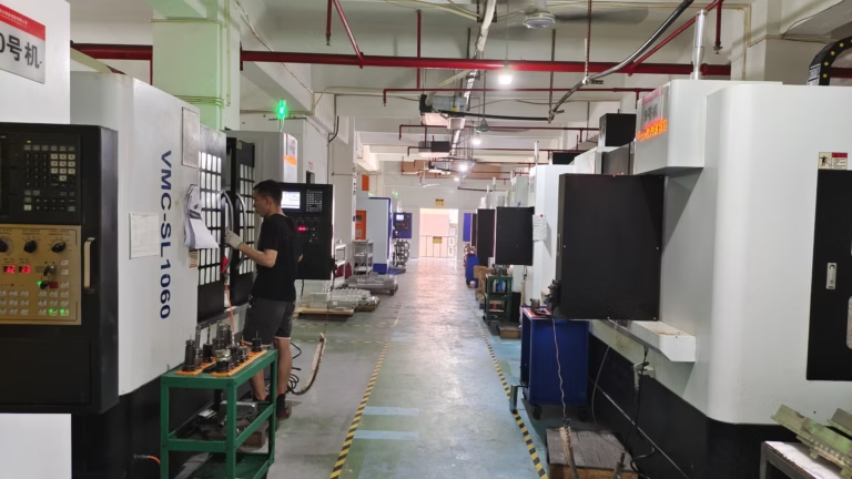
When the joint is going into production, the faces that carry the retention load are the ones worth machining. A printed housing with a CNC-machined catch insert gives you a printed form factor and a predictable, tight-tolerance engagement face. The insert can be POM, PA, or PC, all of which hold strain and wear better than printed polymer.
The same hybrid approach helps when the hook needs a sharp undercut that printing cannot produce cleanly. Print the body, machine the hook, bond or press it into place. The joint then behaves like a machined joint, because the load-bearing geometry is machined.
Questions engineers ask about printed snap fits
How do I calculate the deflection I can get from a printed cantilever?
Use the standard beam equation for the deflection you need, then check the resulting root strain against the allowable strain of the printed material. For a rectangular beam, ε = 1.5 × t × y / L². If the strain exceeds the allowable value, lengthen the beam or reduce the deflection rather than thinning the beam, because thin beams print poorly and twist.
Apply a reduction factor to the datasheet strain limit. FDM parts loaded across layers can lose 30–40% of the molded value. Test a coupon to confirm the number before you commit to the design.
Which print orientation gives the strongest snap fit beam?
Orient the beam so its length runs in the XY plane and the bending load stays within a layer rather than pulling layers apart. On an FDM printer, that means the beam lies flat on the bed with layer lines running along the beam.
Avoid printing the beam standing vertically. In that orientation the bending stress acts across the layer boundaries, which is the weakest direction of the part.
What clearance should I use between the hook and the catch?
For FDM, start at 0.25–0.4 mm on the engagement face and 0.15–0.3 mm on sliding surfaces. SLS can hold 0.15–0.25 mm. SLA can go tighter, but measure a cured coupon because post-cure shrinkage changes the final size.
Print a test coupon that reproduces the full joint stack, including the wall thickness and the catch, before you cut the clearance into the production model.
When should I switch from a printed snap fit to a machined one?
Switch when the joint must cycle hundreds of times, when the engagement face needs a tolerance tighter than the printer holds, or when the undercut cannot be printed without support that damages the mating surface.
A common approach is a printed housing with a machined catch insert in POM, PA, or PC. The load-bearing geometry is machined to a tight tolerance and the housing keeps the printed form factor.
Do I need to anneal or post-process a printed snap fit?
Annealing can improve layer bonding in some semicrystalline polymers, but it also shrinks the part and can warp thin beams. If you anneal, do it before you measure the clearance, because the dimensions will change.
For SLA parts, the post-cure step is mandatory and it hardens the resin. Cure fully, then measure. An under-cured part will keep changing shape after assembly.
Can you quote both the printed prototype and the machined insert?
Yes. Upload the CAD and you get a quotation plus a DFM analysis within 12 hours. We run 3D printing and CNC machining under one roof, so the prototype and the production insert can be made to the same drawing.
Uploads are kept confidential and an NDA is available on request. No minimum order quantity, from one prototype to 10,000+ part runs.
Send us the joint and we will check the strain
Upload your CAD and get a quotation plus a free DFM review of the snap fit geometry within 12 hours.
12-hour quoteFree DFM analysis100% inspection









