
5 Key Advantages of CMS CNC 5-Axis Machining for Precision-Driven Manufacturers
This page explains what simultaneous 5-axis machining actually changes on the shop floor, written for engineers and sourcing teams who specify the parts. You will see where the five advantages come from, which part features justify the setup, and when a 3-axis or mill-turn route is the better call.
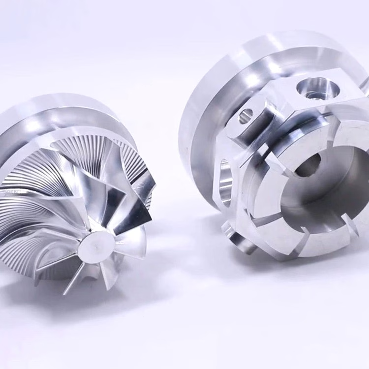
What 5-Axis Machining Changes, and What It Does Not
The five advantages below are process effects, not marketing claims. Each one traces back to a specific machine behavior you can verify on a drawing.
Fewer Setups, Fewer Chances for Error Stack-Up
On a 3-axis mill, every new face of the part means a new fixture, a new zero, and a new chance to lose position. An undercut, an angled oil gallery, or a 35° mounting pad usually forces a second or third op. Each re-clamp adds a small locating error, and those errors accumulate across the part. Five-axis simultaneous motion removes most of that. The tool tilts and rotates around the part, so one coordinate system covers five faces.
We run 16 simultaneous 5-axis machining centers, including large-format machines with travels up to 4,000 × 400 × 150 mm. That range matters for parts like long structural rails, inverter housings, and manifold bodies where the critical bores sit on different planes. If the part fits in one work envelope, we hold ±0.005 mm across those faces without breaking the setup.
Process consolidation also shortens the route. Fewer programs, fewer fixture builds, less queue time between operations. A part that needed three machines and a week of scheduling can move through one machine and one queue. For teams under schedule pressure, that is often the deciding factor, not the surface finish.
- 1Good fitParts with angled holes, undercuts, or features on more than three faces.
- 2Poor fitFlat plates with features on one face only. A 3-axis machine is cheaper and faster.
- 3Check firstWhether the part can be clamped rigidly through the full rotation.
Better Surface Finish and Tighter Dimensional Control
When a ball-nose cutter reaches a contoured surface, the tool contact point shifts constantly. On a 3-axis machine, the effective cutting speed drops near the tool tip, which smears material and leaves witness marks. Tilting the tool keeps the contact point on the cutting edge where the surface speed is stable. The result is a more even Ra across the whole surface, not just on the flat sections.
Tool deflection is the other half of the story. A long tool in a deep cavity bends under cutting force, and the bend shows up as taper or chatter. Five-axis positioning lets us use a shorter, stiffer tool and keep the load near the tool axis. We routinely hit Ra 0.8–1.6 μm as machined, and Ra 0.2–0.8 μm on finishing passes with the right tool and stepover.
Dimensional accuracy follows the same logic. Less vibration means less variation, and one setup means no re-datum error. On bores and bearing seats, we hold ±0.005 mm (±0.0002 in) where the drawing calls for it. Every part is checked before shipment, with raw material verification, in-process monitoring, and a final inspection report available on request.
- 1Best finish pathTilted ball-nose finishing with constant contact on the cutting edge.
- 2Watch forTool overhang beyond 4× diameter. Step up to a larger shank instead.
Material and Cycle Time Savings Through Near-Net Shape Cuts
Scrap and rework usually come from setups, not from the cutting itself. A mis-located second op re-cuts a bore that was already correct. Consolidating operations removes that class of failure. On near-net shape work, we also remove less air. The tool follows the actual part contour instead of a series of step-downs, so the cycle spends more time in the cut and less time repositioning.
That matters most on expensive stock. Titanium TA1, TA2, and TC4 (Ti-6Al-4V) billets, Inconel, and 17-4PH stainless are priced by weight, and every roughing pass that removes excess stock is money on the floor. Adaptive toolpaths with constant chip load let us run higher feed rates in the roughing stage while keeping tool engagement steady. Thin-wall sections stay stable because the cutting force stays predictable.
We take parts from one prototype to 10,000+ piece runs with no minimum order quantity. At the prototype stage, the value is in getting the geometry right in one setup. At the production stage, it is in holding the cycle time flat as volumes rise.
- 1Where savings landRoughing passes on titanium, Inconel, and other high-cost alloys.
- 2Where they do notSimple prismatic parts. The programming overhead can outweigh the gain.
Setup Route by Part Feature
Use this as a first filter before requesting a quote. It describes typical routing, not a fixed rule for every drawing.
| Part feature | Typical route | Why |
|---|---|---|
| Features on one face, flat part | 3-axis mill | One setup is enough; lowest cost per part |
| Features on two opposite faces | 3-axis or 4-axis | Simple indexing covers the second face |
| Angled holes plus deep pockets | 4-axis or 5-axis | Depends on angle range and tool access |
| Undercuts and contoured surfaces | 5-axis simultaneous | Tool tilt reaches geometry a 3-axis cannot |
| Bores on five faces, tight position | 5-axis simultaneous | Single datum removes re-fixture error |
| Turned body with milled side ports | Mill-turn center | One chucking for round and prismatic features |
| Long rail over 2,000 mm | Large-format 5-axis | Travels up to 4,000 × 400 × 150 mm |
| Thin-wall titanium housing | 5-axis with adaptive paths | Controlled engagement limits wall deflection |
Longer Tool Life and More Predictable Process Behavior
Tool shock is what kills carbide. When a cutter enters a corner on a 3-axis path, the engagement angle jumps and the edge takes a sudden load. Five-axis tool orientation keeps the engagement angle closer to constant, so each tooth removes a similar chip. The edge wears evenly instead of chipping. On hardened steel and Inconel, that difference shows up as more parts per tool, not just a nicer finish.
Stable engagement also makes the process easier to monitor. Spindle load, axis torque, and acoustic signals stay in a narrower band, so an out-of-trend reading means something real. We log in-process data across the run and compare it against the proven program. When a reading drifts, we stop and check the tool, the fixture, or the stock condition before the next part is cut.
This is not full predictive maintenance in the software sense. It is disciplined process control: known tool life, known load signature, and a documented reaction when either moves. For buyers, the practical output is a qualification rate of 99.99% on shipped parts, backed by 100% inspection.
- 1Constant chip loadKeeps cutting force steady and reduces edge chipping on hard alloys.
- 2Tool life trackingReplace on count or load trend, not on operator judgment.
Ready for Hard Alloys, Composite Stacks, and Printed Preforms
Newer designs push into materials that punish a light machine. Inconel and titanium need low surface speed, high pressure coolant, and a rigid setup. Magnesium AZ31B and AZ91D need chip control and careful handling. Carbon fibre and composite stacks need sharp tooling and dust extraction rather than flood coolant. Five-axis centers handle these because the tool can be oriented to the best cutting direction for each feature, and the machine structure is built for the load.
Additive preforms are a growing case. A printed near-net blank often has a rough surface and a non-uniform skin. The first machining op has to establish a clean datum from an irregular shape. We probe the blank, map the actual surface, and adjust the program before cutting. Five-axis access lets us reach the datum faces and the critical features in the same setup, so the printed geometry and the machined geometry stay aligned.
GreatLight has run these routes since 2011 across three wholly-owned plants and 7,600 m² of floor space, with 150 technicians and 127 high-precision CNC machines. Our quality system is certified to ISO 9001:2015, IATF 16949:2016, ISO 13485:2016, and ISO 27001:2022. Uploads are handled as confidential, and an NDA is available on request.
- 1Hard alloysInconel, Ti-6Al-4V, 17-4PH. Rigid setup and constant engagement matter most.
- 2CompositesCarbon fibre and stacked materials need sharp edges and dust control.
- 3Printed preformsProbe and re-datum before the first cut. Do not trust the nominal model.
Questions Engineers Ask Before Specifying 5-Axis
How do I know if my part actually needs 5-axis simultaneous motion?
Start with the feature list. If the critical features sit on more than three faces, or if the part has undercuts, angled holes, or contoured surfaces that a 3-axis tool cannot reach at the correct angle, simultaneous 5-axis is the straightforward route.
If every feature is on one face, or on two faces that can be reached by simple indexing, a 4-axis or 3-axis machine will usually cost less and hold the same tolerance. Send the drawing and we will tell you which route we would take.
What tolerance and surface finish can you hold on a 5-axis part?
We hold ±0.005 mm (±0.0002 in) on critical features where the drawing requires it. As-machined finish is typically Ra 1.6–3.2 μm, with Ra 0.8–1.6 μm on standard finishing passes and Ra 0.2–0.8 μm when a finer stepover and tool are specified.
Achievable values depend on the material, wall thickness, and feature geometry. Deep cavities with long tool overhang are the usual limiting case.
Does 5-axis always lower the part cost?
No. It lowers cost when the part would otherwise need several setups, several fixtures, or several machines. The programming and setup time for 5-axis is higher, so on a simple flat part the 3-axis route is cheaper.
The break-even usually arrives when the 3-axis route needs a third operation or a dedicated fixture.
How do you handle thin walls and vibration on 5-axis parts?
We control the engagement angle and take lighter, faster passes rather than heavy cuts. Adaptive toolpaths keep the radial engagement constant, which keeps cutting force predictable and limits wall deflection.
Where the wall is very thin, we leave support material and remove it in the final passes, or adjust the sequence so the stiffest sections are machined last.
Can you machine a printed blank or casting in the same setup as the finished features?
Yes, when the blank fits the work envelope. We probe the incoming surface, establish a real datum from the measured geometry, and shift the program accordingly before cutting.
This is common on near-net printed preforms and on castings where the as-cast skin varies from part to part.
What do you need from us to quote a 5-axis part?
A 3D model in STEP or IGES, a 2D drawing with tolerances and datum callouts, the material grade, the surface finish, and the quantity. Note any features that must be machined in one setup.
We return a quotation and a free DFM analysis within 12 hours, and production can start within 24 hours of approval. Standard parts ship in 3–5 days.
Send Us the Drawing, We Will Tell You If 5-Axis Is the Right Route
Upload your model and tolerances for a free DFM review. You get a quotation and a routing recommendation within 12 hours, and every part is inspected before it ships.
12-hour quote and DFM±0.005 mm tolerance100% inspection before shipmentNDA available on request









