
7 Best Metal CNC Machines for Precision Machining in 2024
A shop-floor look at seven machine classes that decide metal cnc machines precision, from five-axis centers to Swiss-type lathes. Written for engineers and buyers who have to pick a process, not a brochure. You will know which class fits a given part feature and when it does not.
What This List Is, and What It Is Not
Seven machine classes, judged by the features they can hold, not by spec-sheet peaks.
Five-Axis Machining Centers: One Setup, Fewer Stacked Errors
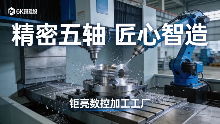
A simultaneous five-axis center moves the tool and the workpiece on five interpolated axes at the same time. The practical gain is not speed. It is that contoured faces, undercuts and angled holes can be cut in one clamping cycle instead of three. Every re-fixture adds a locating error, and those errors stack. Take the re-clamps out and the stack gets shorter.
This class suits turbine blades, impellers, medical implants, engine housings and any part where the functional surfaces sit at unrelated angles to each other. It also suits parts with deep, steep side walls that a three-axis spindle cannot reach without a long, thin tool. A shorter tool is a stiffer tool, and stiffness is what keeps a wall straight.
The limiting factor is programming and thermal behavior, not the iron. A five-axis machine running a generic post-processor will chatter, leave witness marks on tangencies and drift over a long cut as the spindle and frame warm up. We write per-job post-processors and let the machine run a warm-up cycle before the first finishing pass, so the compensation table reflects the actual thermal state of that shift.
Where it is the wrong choice: flat plates, simple brackets and prismatic parts with features on one or two faces. A three-axis machine with a good vise will hold the same tolerance for less setup time and less spindle-hour cost.
A 16-station five-axis fleet is not there to sell five axes. It is there so a part gets routed to the axis count its geometry actually needs.
- 1Good fitBladed and contoured geometry, undercuts, angled ports, single-setup finishing
- 2Poor fitFlat plates and prismatic parts with features on one or two faces
- 3WatchPost-processor quality, thermal drift on long finishing passes, tool reach versus stiffness
Mill-Turn and Swiss-Type Lathes: Turning and Milling in One Hit
A mill-turn center carries a live tool turret or a B-axis head on a turning platform, so it can turn an OD, mill a flat, drill a cross hole and cut a thread without the part leaving the spindle. Hydraulic valve bodies, aerospace fittings, sensor housings and motor shafts are the usual candidates. These parts share a trait: a turned feature and a milled feature that are dimensionally tied to each other.
The gain shows up as fewer operations and fewer datums. If a bore and a milled pad are both referenced to the same spindle, their relationship is set by the machine, not by how well an operator seated the part in a second fixture. Cycle time drops because there is no queue between operations and no re-chuck.
Swiss-type lathes take the same logic to small, long parts. The guide bushing supports the stock right at the cutting zone, so a Ø6 mm shaft with a 10:1 length-to-diameter ratio can be turned without deflection. Below roughly Ø20 mm and above 3:1 L:D, this is often the only stable route. Above Ø32 mm the guide bushing stops helping and a chucker or a mill-turn center is the better call.
The trade-off is programming complexity. Simultaneous turning and milling on one platform is unforgiving of a careless toolpath. It also ties up an expensive machine on features that a two-operation route could handle. For low-volume work with loose cross-feature tolerance, splitting the job across a lathe and a mill is often cheaper.
- 1Good fitRotational parts with cross features tied to a turned datum
- 2Swiss-type fitSmall diameter, long slender shafts, high L:D ratio
- 3Poor fitLarge-diameter parts, simple turn-only work, loose cross-feature tolerance
Grinding and Finishing: When Milling Runs Out of Resolution
Milling leaves a scallop pattern set by the tool nose radius and the stepover. Grinding cuts with a wheel made of abrasive grit, and it can hold roundness and surface roughness that no milling cutter will reach. Hydraulic sealing faces, optical mounts, bearing journals and spindle tapers live in this range. If the drawing calls for Ra 0.2–0.8 μm and a roundness figure in the sub-micron range, the part is a grinding part.
The reason is contact geometry. A milling cutter touches the work at a point, and that point deflects under load. A grinding wheel touches along a line and removes material in very small increments, so the force per unit of cut is low and the resulting form error is small. Cylindrical and surface grinders also let the operator dress the wheel and re-establish geometry between parts, which milling cannot do in-cycle.
Hardness is the other driver. A 58 HRC tool steel insert or a hardened 440C shaft will not mill to a fine finish without wrecking the cutter. Grinding does not care about hardness. For parts that are heat treated after rough machining, we leave grinding stock and finish after treatment, because heat treatment moves the part.
The catch is setup. Grinding needs a dressed wheel, a true center or a magnetic chuck, and a part that can be held without distortion. Thin walls and unsupported webs will spring. For those, a fine milling pass with a small stepover plus bead blasting or polishing gets close enough, and it costs less.
- 1Good fitSealing faces, bearing journals, tapers, hardened parts, sub-micron roundness
- 2Poor fitThin walls, unsupported webs, parts that cannot be held without spring
- 3Sequence noteLeave grinding stock on parts that get heat treated after roughing
High-Speed Die and Mold Machining: Deep Cavities and Hard Steel
Die and mold work means deep pockets, thin ribs, sharp internal corners and often a hardened workpiece. The machine class built for it runs high spindle speeds with a thermally stable frame, and it is paired with CAM that keeps tool load constant. Mold inserts, die casting dies, injection tooling and electrode stock come through this route.
Two things separate a mold-capable machine from a general mill. First, the spindle must hold speed under load, because a small ball cutter at high rpm loses torque fast and the surface finish goes with it. Second, the control must handle look-ahead on thousands of short moves without stalling. A cavity made of 20,000 tiny segments will show every pause as a mark on the wall.
Hard milling is the other half. Once a cavity is heat treated to 50 HRC and above, the finishing pass has to be taken with a coated carbide or ceramic tool on a rigid machine. This replaces some EDM work, which shortens the process chain, but it demands that the roughing stock be even. A hard-milling pass that meets a lump of leftover stock will chip the cutter.
Where it does not pay: large, shallow, open geometry. A three-axis machine with a big envelope will clear that faster. Reach matters too. A deep cavity narrower than 2:1 depth-to-width needs a long tool, and long tools deflect. On those features we rough with a larger cutter and finish with a smaller one, or fall back to EDM for the corners.
- 1Good fitDeep cavities, thin ribs, hardened inserts, tooling with sharp internal corners
- 2Poor fitLarge shallow open geometry; very deep narrow slots that force long tools
- 3RequirementEven roughing stock, constant tool load, look-ahead that does not stall
Micro-Machining and Heavy-Duty Five-Axis: Two Ends of the Same Question
Micro-machining centers use small spindles, fine feedback resolution and light, fast moves. The parts are small: connector housings, optical benches, implant components, tiny gears. What decides success here is not the machine alone but the tool. A Ø0.3 mm end mill has almost no stiffness, so runout has to be held to a few microns and the toolpath has to keep radial engagement low. Thermal growth of a few microns is a real fraction of the feature size.
Heavy-duty five-axis sits at the opposite end. Large travel, a big rotary table and a frame built to absorb interrupted cuts. Structural brackets, housings and parts machined from plate stock up to 4,000 mm come through this class. The question is not whether the machine can reach the feature, but whether it can hold the feature while removing material at a rate that makes the job viable.
Both classes are often quoted on the same RFQ, and that is where quotes go wrong. A micro part routed to a large machine gets a tool that is too big and a spindle that cannot spin fast enough. A large structural part routed to a small high-speed machine gets a job that takes three times as long. Matching the class to the feature size is the first decision, before tolerance.
For our own work: 27 three-axis machines cover the prismatic middle, 12 four-axis mills handle parts that need indexing, 16 simultaneous five-axis centers take the contoured and single-setup work, and the largest envelope is 4,000 × 400 × 150 mm. Parts are routed by geometry, not by which machine is free.
- 1Micro fitSub-millimeter features, small bores, fine slots, high spindle speed
- 2Heavy-duty fitLarge plate and structural parts, interrupted cuts, high metal removal rate
- 3Common errorRouting a part by tolerance alone and ignoring feature size
Machine Class by Part Characteristic
A starting point for routing, not a substitute for a DFM review.
| Machine class | Typical parts | Holds best | Wrong when |
|---|---|---|---|
| Five-axis center | Impellers, implants, housings | Contoured faces, angled holes, one setup | Flat prismatic parts, few faces |
| Mill-turn center | Valve bodies, fittings, shafts | Turned and milled features on one datum | Simple turn-only work |
| Swiss-type lathe | Small long shafts, pins | Slender parts, high L:D ratio | Diameter above Ø32 mm |
| Grinder | Seals, journals, tapers | Roundness, Ra 0.2–0.8 μm, hard steel | Thin walls, unsupported webs |
| Die and mold mill | Mold inserts, die casting dies | Deep cavities, hard milling | Large shallow open geometry |
| Micro-machining center | Connectors, small gears | Sub-millimeter features, fine slots | Parts over a few centimeters |
| Heavy-duty five-axis | Structural brackets, plate work | Large envelopes, heavy cuts | Small fine-feature parts |
Questions Engineers Ask Before Routing a Part
How do I choose between five-axis and a three-axis plus fixtures?
Count the clamping cycles. If the part needs three or more setups, or if features on different faces are tied to each other by a tight tolerance, five-axis usually wins on total error and on lead time.
If the part is prismatic and most features sit on one or two faces, a three-axis machine with a good vise is faster and cheaper. The tolerance is not the deciding factor. Setup count and feature orientation are.
What tolerance and finish can GreatLight hold?
Positioning tolerance goes to ±0.005 mm (±0.0002 in). Surface finish depends on the process: Ra 0.2–0.8 μm after fine finishing or grinding, Ra 0.8–1.6 μm for a standard machined finish, Ra 1.6–3.2 μm as machined.
These are process capabilities, not a blanket promise on every feature. Wall thickness, tool reach and material hardness all move the number. Send the drawing and we will tell you which features are tight and which are routine.
Which materials cause the most trouble on precision work?
Titanium and Inconel move under cutting heat and work-harden at the surface, so toolpaths have to keep the cutter engaged instead of rubbing. Magnesium AZ31B and AZ91D cut easily but need chip control because fine chips are a fire risk.
Beryllium copper machines well but the dust needs handling. Aluminum 7075 holds a good finish but stresses out of plate stock if too much material is removed in one pass. We plan roughing and stress relief around the material, not just the geometry.
Can one shop cover prototype quantities and production runs?
Yes. There is no minimum order quantity, so a single prototype and a 10,000+ part run go through the same process planning. The difference is fixture investment and whether we hold the setup for repeat orders.
For prototypes we often machine from billet on a five-axis center to skip soft tooling. For runs we look at die casting, vacuum casting or dedicated fixturing once the design is frozen.
How is precision verified before shipment?
Every part gets 100% inspection before shipment, with raw material check, in-process monitoring and final inspection. Inspection reports are available on request.
For first articles we run a full dimensional report. Where a drawing calls for it, we run process capability studies. The shop holds ISO 9001:2015, IATF 16949:2016, ISO 13485:2016 and ISO 27001:2022.
What happens to my files and design data?
Uploads are treated as confidential. We sign an NDA on request, and an ISO 27001:2022 information security system covers how files are stored and who can open them.
A quotation and DFM analysis come back within 12 hours, so you can see manufacturability notes before committing to an order.
Send the Drawing, Get a Routing Answer
Upload your part and we will come back with a machine class, a DFM note on the tight features, and a quotation.
12-hour quote100% inspectionNo minimum order quantity









