
7 Vertex CNC Mistakes That Are Costing You Thousands
Sharp internal corners, compound intersections and small geometric vertices drive most of the hidden cost in precision parts. This page breaks down seven vertex CNC mistakes that are costing you thousands, what each one looks like at the spindle, and how to decide when a feature is worth the extra cycle time. Written for engineers and buyers who sign off on the drawing.
Where vertex cost actually comes from
A vertex is any point where two or more machined surfaces meet at a sharp or compound angle. Cost hides there, not in the open faces.
Deflection and cutter geometry at sharp vertices
Mistake #1 is treating an acute internal vertex like a gentle radius. When a cutter enters a corner where the wall angle changes abruptly, radial engagement jumps and lateral force spikes. A standard carbide end mill can deflect several microns, which shows up as a witness mark or a dimension that drifts out of tolerance. Program the same speeds and feeds you use for straight-line cutting and the corner will tell you about it.
The fix is not exotic. Reduce chip load through the corner, or let a smaller tool clear the vertex before a larger one finishes the wall. Some shops tilt the tool so the cutting edge meets the vertex at a favorable lead angle. That spreads the load and keeps tool life predictable. A single rework pass on a bracket costs far more than the extra minutes this adds.
Mistake #2 is picking cutter geometry without thinking about the vertex itself. A sharp-cornered tool leaves a true corner but concentrates stress and chips easily. A small corner radius distributes load and lasts longer, yet it cannot produce the geometry a print may demand. The decision belongs in the process plan, not in the operator's hands at the machine.
- 1Acute internal vertexReduce chip load and check deflection before accepting the corner radius.
- 2Corner radius choicePick the radius from the drawing and the load, not from what is in the tool crib.
- 3Tool tiltA lead angle spreads cutting force and protects the vertex edge.
Heat at concentrated vertices and tolerance chains
Mistake #3 is ignoring thermal distortion where mass concentrates. At a vertex, walls often meet in a thick section or a thin web, and the cutting heat does not leave evenly. Titanium, Inconel and even 6061-T6 will expand locally, then relax as the part cools. The vertex you measured hot is not the vertex the customer receives. Rough, rest, then finish with a cool-down in between.
Mistake #4 is chaining tolerances across multiple vertices without a common datum. Stack ±0.005 mm from vertex A to B to C and the error at the far vertex can exceed 0.03 mm. That is enough to misalign an assembly. Ask which vertex controls fit and which only controls appearance, then reference every critical one to a shared datum.
Blindly following a print that chains dimensions is a cost risk for both sides. Flag it at quoting, not after the first article fails.
Setup error on multi-vertex parts and finish specs
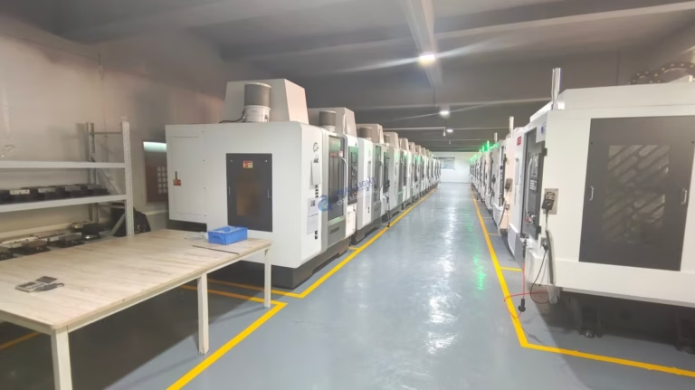
Mistake #5 is underestimating how setup error compounds. Every re-fixturing adds its own positional error, and a part with six vertices across four setups can accumulate error that no single operation looks responsible for. Fewer setups mean fewer error sources. On our 16 simultaneous five-axis centers we reach five faces in one clamping, which holds vertex-to-vertex position where the design needs it.
That is not an argument for five-axis everywhere. On a simple bracket, three-axis with a good fixture is cheaper and just as accurate. The judgment call is how many critical vertices depend on each other. If two vertices must align in assembly, machine them in the same setup.
Mistake #6 is specifying one surface finish across every vertex. A uniform Ra 0.8 μm on a small internal corner forces very fine step-overs, and cycle time climbs out of proportion. Match finish to function instead.
- 1Setup countEach re-fixturing adds positional error that stacks across vertices.
- 2Function-based finishSealing and bearing vertices need fine Ra; clearance corners rarely do.
- 3Same-setup ruleMachine vertices that must align in one clamping wherever possible.
Matching vertex type to machining approach
Use this to decide where to spend machine time and where the drawing is asking for more than the function needs.
| Vertex type | Typical risk | Suggested approach | Finish target |
|---|---|---|---|
| Acute internal corner | Tool deflection, witness marks | Smaller cutter, reduced chip load | Ra 1.6–3.2 μm |
| Compound 3D intersection | Setup error, mismatch | Five-axis, single clamping | Ra 0.8–1.6 μm |
| Thick-to-thin transition | Thermal distortion | Rough, cool, then finish | Ra 0.8–1.6 μm |
| Sealing face vertex | Leak path, flatness | Fine step-over, in-process check | Ra 0.2–0.8 μm |
| Clearance corner | Over-machining, cost | Standard pass, no extra work | Ra 1.6–3.2 μm |
Skipping in-process metrology on buried vertices
Mistake #7 is the quiet one. Some vertices cannot be reached once the part is assembled, and a final inspection after assembly will not see them. If the vertex is buried by a cover, a mating plate or a weldment, measure it while it is still accessible or accept that you cannot prove the dimension.
Put the check in the process, not at the end. Probe the vertex after the operation that creates it, while the part is still on the machine and the error can be corrected. A first-article report on a buried vertex is worth more than a final report that never touches it.
This is also where a DFM review pays for itself. If we can see at quoting that a vertex will be inaccessible later, we say so before the first chip.
Questions engineers ask about vertex machining
When is a sharp internal vertex not worth the cost?
When it carries no function. If the corner is clearance or cosmetic, a small radius removes the deflection risk and the extra inspection step.
Keep the sharp corner only where a mating part or a fluid path actually needs it.
How do you hold position across several vertices on one part?
Reduce the number of setups and reference every critical vertex to a common datum. On parts with compound geometry, five-axis machining reaches multiple faces in one clamping.
We hold ±0.005 mm where the drawing requires it, and we tell you when a tolerance chain will not survive the process.
Does every vertex need a fine surface finish?
No. Sealing faces and bearing surfaces justify Ra 0.2–0.8 μm. Clearance corners usually run fine at Ra 1.6–3.2 μm.
Applying one finish callout everywhere is one of the vertex CNC mistakes that are costing you thousands in cycle time.
What materials are hardest at concentrated vertices?
Titanium (TC4 / Ti-6Al-4V), Inconel and thin-wall aluminium sections move the most under cutting heat. They need rough-and-rest cycles before finishing.
6061-T6 and 7075 are more stable but still move when a vertex sits next to a thin web.
Can you check a vertex that is buried after assembly?
Only while it is still accessible. We probe the feature after the operation that creates it, then document the result.
Once it is covered, no final inspection can prove the dimension. Plan the check earlier.
What do you need to review vertex risk at quoting?
A 3D model or a print with the datum scheme, the material, and the finish callouts. That is enough for a free DFM analysis within 12 hours.
Uploads stay secure and confidential, and an NDA is available on request.
Send us the drawing before the vertex costs you
We review vertex geometry, datum chains and finish callouts at quoting, then tell you which features are worth the machine time. Quote and DFM analysis back within 12 hours.
12-hour quote + DFM100% inspection before shipmentNDA on request









