
A Beginner Guide to CNC Machines
This page explains what beginner CNC machines actually do, how the main subsystems work together, and which machine configuration fits a given part. It is written for design engineers, mechanical engineers, and sourcing staff who need to read a drawing and decide what to quote. You will finish with a clear idea of when 3-axis is enough and when a 4-axis or 5-axis machine earns its cost.
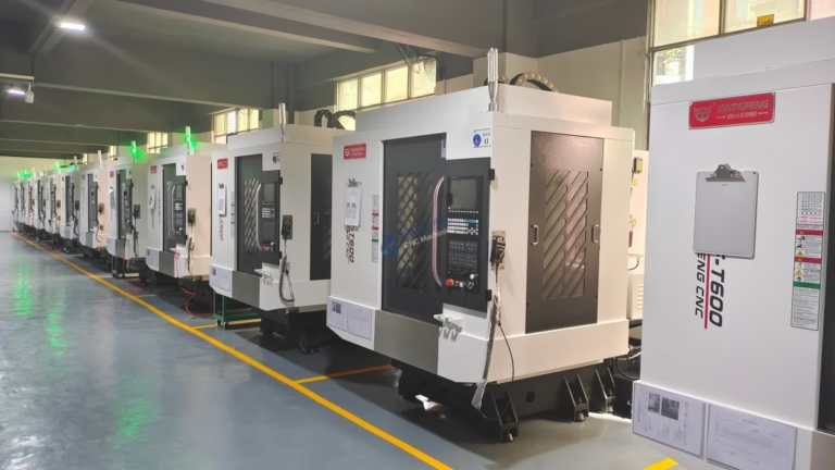
What a CNC machine is, in plain terms
A computer moves a cutting tool along a path defined by a CAM program. The machine repeats that path exactly, on part one and on part ten thousand.
The core parts and what each one does
CNC stands for computer numerical control. A CAM program turns a CAD model into toolpath coordinates, and the machine controller reads those coordinates as motion commands. The spindle holds the tool and spins it. The axes move the tool or the workpiece along the programmed path. The machine repeats the same motion every cycle, which is why it holds size across a run.
Accuracy comes from the frame, not from the software. A cast iron or polymer concrete base absorbs cutting vibration, and linear guideways or box ways keep the axes straight under load. A rigid machine can take a heavier cut, and a heavier cut usually means fewer passes and less tool deflection.
The control loop closes at the servo. Encoders on each axis report position back to the controller, which corrects any error in real time. On a thermal-stable machine, that loop is what keeps a Ø 50 mm bore at Ø 50 mm from the first part to the last.
- 1SpindleHolds the tool. Speed and torque decide which materials the machine can cut efficiently.
- 2AxesLinear X, Y, Z plus rotary axes. The count sets the geometry you can reach.
- 3ControllerReads G-code, runs the servo loop, manages tool changes and offsets.
- 4WorkholdingVise, chuck, fixture plate, or vacuum table. Poor clamping causes chatter.
3-axis, 4-axis, and 5-axis: what changes
A 3-axis mill moves the tool in X, Y, and Z only. The tool always approaches from the top. This covers flat plates, pockets, slots, stepped faces, and most drilled hole patterns. It is the cheapest configuration per hour and the easiest to program, so it stays the default for simple geometry.
A 4-axis machine adds one rotary axis, usually turning the workpiece around X. That lets you cut on multiple faces of a shaft or a cylindrical part without resetting it. Think of a camshaft, a flanged fitting, or a part with radial holes at several angles. One setup, one position, fewer chances for stacked tolerance error.
A 5-axis machine adds two rotary axes, so the tool can tilt and the table can turn. The tool reaches undercuts, deep cavities, and contoured surfaces at a near-constant angle. Complex impellers, turbine blades, and organic housings often cannot be cut any other way. Five-axis also shortens setups, because the machine reaches five faces from one clamp.
- 13-axisFlat and prismatic parts. Lowest cost, fastest to program.
- 24-axisShafts and cylindrical parts with features around the axis.
- 35-axisContoured surfaces, undercuts, and parts needing many faces in one setup.
Which machine class fits the part
Use this as a starting filter before you ask for a quote. The right answer depends on geometry first, then on quantity.
| Machine class | Travel range | Good fit for | Watch out for |
|---|---|---|---|
| 3-axis compact | 500 × 310 × 200 mm | Small brackets, plates, covers | No access to side faces |
| 3-axis standard | 750 × 1,150 × 550 mm | Mid-size housings and panels | Deep cavities need long tools |
| 4-axis mill | Ø400 mm rotary table | Shafts, cams, radial hole patterns | Rotary axis adds setup checks |
| 5-axis center | 600 × 600 × 600 mm | Contoured and multi-face parts | Higher hourly rate, more programming |
| Large gantry | 4,000 × 400 × 150 mm | Long beams, rails, extrusions | Limited Z depth on tall parts |
Tolerance, finish, and what drives cost
Tolerance is the total allowed size variation. A general machining tolerance of ±0.005 mm is achievable on a rigid machine with the right tool and a temperature-controlled shop, but not every feature needs it. Tightening a tolerance adds inspection time, slower feeds, and sometimes a second operation. Keep only the fits that matter at ±0.005 mm and let the rest run looser.
Surface finish is measured as Ra, the average roughness. As-machined surfaces sit around Ra 1.6–3.2 μm. A fine finish of Ra 0.2–0.8 μm needs a smaller stepover, a sharper tool, and often a finishing pass on a separate setup. If the drawing does not call for it, specify the coarser band and save the cost.
Cost moves with three things: how many setups the part needs, how much material is removed, and how tight the tolerances are. A part that can be cut from one side on a 3-axis machine is cheap. The same part split across four setups on a manual mill is not. Five-axis pays for itself when it collapses several setups into one.
- 1One setup beats fourEach re-clamp adds position error and labor.
- 2Tolerance is per featureApply it where the fit is, not to the whole drawing.
- 3Finish follows toolpathA tighter Ra needs a smaller stepover and more time.
Materials and how they behave on a beginner setup
Aluminum is the usual starting point. Grades like 6061 and 7075 cut fast, hold a good finish, and do not wear tools quickly. If you are new to CNC, aluminum lets you focus on geometry and workholding instead of fighting the material. Stainless 303 and 304 machine well but work-harden if the tool rubs, so keep the feed up and the tool sharp.
Steel grades 1018 and 1045 are common for structural parts, while 4140 and 4340 appear in higher-strength applications. Titanium and Inconel need rigid setups, low cutting speeds, and plenty of coolant. On a light hobby-class machine these materials are slow and hard on tools, which is why most beginners stay with aluminum, brass, and plastics first.
Plastics such as POM, ABS, and PEEK cut easily but can melt or chip if the spindle runs too fast. PEEK and carbon fiber need sharp tooling and good chip evacuation. For any material, the practical limit is not the metal itself, it is whether the machine has the rigidity and spindle power to cut it at a sensible rate.
From CAD model to finished part
The workflow starts with a 3D CAD model. From there, CAM software defines stock size, tool selection, stepover, feed rate, and toolpath strategy. The output is G-code, which the controller reads. A machinist then sets work offsets, loads tools, and runs a first article.
The first article is the moment of truth. Inspectors measure critical features against the drawing, and the machinist adjusts offsets if needed. Once the first part passes, the run continues with the same program and the same offsets. This is why repeatability matters more than any single measurement.
If a feature cannot be reached, the fix is usually a design change, not a bigger machine. A chamfer that allows a tool to enter, a fillet that removes a sharp inside corner, or a small shift in a hole location can turn a five-axis job into a 3-axis job. DFM feedback before cutting saves both time and money.
- 1CADDefines the geometry you want.
- 2CAMDefines the path the tool will follow.
- 3First articleConfirms the setup before the run continues.
Owning a machine vs sending parts out
A desktop or benchtop CNC machine suits learning, prototyping, and low-volume work in soft materials. It teaches feeds, speeds, workholding, and tool wear without a large capital outlay. The limits show up fast: small travel, low spindle power, and deflection on hard materials.
For production parts with tight tolerances, outsourcing to a shop with 5-axis centers and inspection equipment is usually cheaper than buying the machine and learning on the job. A shop that runs 127 high-precision machines and inspects 100% before shipment can hold ±0.005 mm and turn parts in 3–5 days.
The practical split is this: keep a small machine for fixtures, prototypes, and quick edits, and send the parts that need tight tolerance, hard materials, or multi-axis geometry to a supplier. That keeps your engineering time on design instead of on setup.
Common questions from new CNC buyers
What is the difference between a CNC mill and a CNC lathe?
A mill spins the tool and moves it against a stationary workpiece. A lathe spins the workpiece and moves a stationary tool into it. Mills suit flat and prismatic parts; lathes suit round parts like shafts and bushings.
Do I need 5-axis for a simple bracket?
No. A bracket with holes on one face runs well on a 3-axis machine. Five-axis is worth it when the part has contoured surfaces, undercuts, or features on several faces that would otherwise need multiple setups.
How tight a tolerance can a beginner machine hold?
A rigid benchtop machine in aluminum can hold around ±0.05 mm with care. Getting to ±0.005 mm needs a stiffer frame, temperature control, and a proper inspection routine. That is a shop-level capability, not a hobby-level one.
Which file format should I send for a quote?
Send a STEP or IGES file plus a 2D drawing with tolerances, material, and finish. The 3D model defines geometry, and the drawing defines the requirements the model cannot show.
How long does a first CNC part take?
Quotation with DFM feedback is returned within 12 hours. Production can start within 24 hours after approval, and parts typically ship in 3–5 days depending on quantity and finishing.
Can I get a prototype without a large order?
Yes. There is no minimum order quantity, so a single prototype and a 10,000-part run go through the same process. Uploads are kept confidential and an NDA is available on request.
Send a drawing, get a DFM review
Upload a STEP file and drawing. We return a quotation and free DFM analysis within 12 hours, with no minimum order quantity.
12-hour quote100% inspectionNo MOQ









