
A Brief Discussion on Solving Residual Stress Problems in Machine Tool Parts
This page is for engineers and buyers who machine beds, columns, housings and long shafts and then watch them move after finishing. It covers where residual stress comes from, how thermal aging and vibratory aging compare, and the process choices that keep a part stable after the last cut.
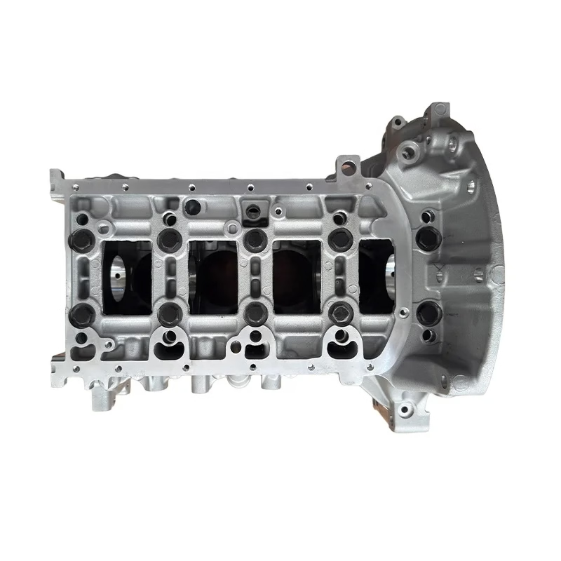
What a brief discussion solving residual stress actually has to answer
Stress relief is not one operation. It is a sequence of decisions that starts at the foundry and ends at the last finishing pass.
Where residual stress in a machine tool casting comes from
Residual stress is locked-in elastic strain. It exists in a part with no external load applied. In machine tool structures it usually arrives from four places: solidification and cooling of a casting, the heat of welding, plastic deformation during rough machining, and the clamping force a fixture applies before the cut even starts.
Cast iron beds and columns are the classic case. The outer skin cools before the core. The core then pulls the skin inward as it contracts, and the part keeps that internal argument for years. Grey iron with a high carbon equivalent releases some of it by itself, which is why a raw casting left in the yard for months behaves better than one moved straight to the planer.
Rough machining adds a second layer. A heavy face mill pass on a 4,000 mm bed removes material from one face only. The balance of the section changes and the part bows toward the machined side. The bow may be 0.3 mm or it may be 1.5 mm, and it is not the same on every casting from the same pattern.
Welded frames are worse. A welded steel base has a heat-affected zone along every seam, and the shrinkage stress there can exceed the yield strength of the parent plate locally. That stress does not disappear when the weld cools. It redistributes, and the frame moves when you cut the first mounting pad.
- 1SolidificationSkin cools first, core contracts later, stress stays in the section
- 2WeldingShrinkage in the heat-affected zone locks in high local stress
- 3Rough machiningRemoving one face unbalances the section and the part bows
- 4ClampingFixture force adds elastic strain that springs back after unclamping
Thermal aging versus vibratory aging: what each one can and cannot do
Thermal aging, sometimes called stress relief annealing, holds the part at a set temperature long enough for the material to creep and redistribute internal strain. For grey iron the soak is typically in the 500–600 °C band with a controlled cool-down. For welded steel frames it runs higher, often 600–650 °C, then cools slowly enough to avoid creating fresh thermal stress.
The method works, and it works on thick sections. That is its advantage. Its cost is energy and distortion. A 4,000 mm bed needs a furnace large enough to hold it, and the slow cool-down ties up that furnace for days. If the cool-down is rushed, the part leaves the furnace with a new stress pattern that is worse than the one you started with.
Vibratory aging, also called vibratory stress relief, shakes the part at a controlled frequency and amplitude so that local plastic flow relaxes the peaks of the stress field. Energy use is a small fraction of a furnace cycle and there is no scale to remove afterward. The catch is setup. The part has to be supported at defined points, driven at a defined point, and the vibration direction has to match the geometry. Get that wrong and the treatment looks successful on the chart while the part still moves.
Sub-resonant vibration is the common industrial version. It is gentle on the part but limited in how deep it reaches. Thin-wall and slender parts respond well. A 200 mm thick iron bed does not. That thickness limit is the main reason vibratory aging has not replaced thermal aging in machine tool work.
- 1Thermal agingDeep reach, works on thick castings, high energy, risk of new distortion
- 2Vibratory agingLow energy, no scale, needs correct support and drive points
- 3Pick by sectionUnder roughly 50 mm vibratory helps; thick beds still want furnace time
- 4Not either-orVibratory after rough machining can top up a furnace cycle
Process comparison for residual stress relief
Typical bands for machine tool structures. Exact parameters depend on material and section.
| Method | Best suited to | Main limit |
|---|---|---|
| Thermal aging | Thick iron and steel castings, welded frames | Energy cost, long furnace cycle, scale removal |
| Vibratory aging | Slender shafts, thin-wall housings, weldments | Setup sensitive, shallow reach on thick sections |
| Natural aging | Low-volume heavy beds with time to spare | Months of floor space, not predictable |
| Rough then finish | All parts that will be finish machined | Adds a setup, needs stock left for the finish pass |
| Stress-relief cut | Thin plates that distort after facing | Removes little material, must be planned in |
Sequencing stress relief with machining: rough, relieve, finish
The most reliable pattern in machine tool work is rough machine, stress relieve, then finish machine. Roughing removes the bulk of the stock and releases the imbalance that comes with it. The relief step then works on the part in its near-final shape, so the stress it removes is the stress that would otherwise move the finished geometry.
Stock allowance matters here. If you rough to within 0.2 mm and then run a furnace cycle, the part may move more than 0.2 mm and you have no material left to correct it. A practical rule is to leave 0.8–1.5 mm per side on critical faces, more on long beds where bow is likely. The finish pass then cuts the part to size in its relaxed state.
For welded frames, the relief step belongs after welding and before any machining of mounting pads. Cutting pads first and relieving afterward wastes the setup, because the pads move during the cycle.
On our 5-axis and mill-turn centers we often hold the part in a single setup for the finish operation. That removes the re-clamp error, but it does not remove residual stress. A part that was never relieved will still walk, no matter how good the setup was.
- 1RoughRemove bulk stock, expect the part to bow toward the cut face
- 2RelieveFurnace or vibratory cycle on the near-final shape
- 3FinishCut to tolerance after the part has settled
- 4AllowanceKeep 0.8–1.5 mm per side on critical faces before the cycle
Which parts need aging and which ones can skip it
Not every part needs a stress relief cycle. A small aluminium bracket machined from 6061-T6 plate and used at room temperature will not move enough to matter. The plate itself was rolled and stretched at the mill, and for a part under 200 mm the residual stress is usually below the level that shows up in a ±0.005 mm tolerance.
The parts that do need it share traits: large envelope, uneven section, a critical flatness or parallelism callout, and a long service life at a stable temperature. Machine tool beds, columns, saddles, spindle housings, granite-alternative polymer bases and long lead screw supports all fall into this group.
A useful test is the ratio of longest dimension to wall thickness. Above roughly 20:1, distortion after machining becomes likely and relief should be planned. Below 10:1, a controlled roughing strategy with a light finish pass is often enough.
Material choice shifts the answer too. Ductile iron and normalized 4140 respond well to thermal relief. Some high-strength aluminium grades and titanium lose a portion of their mechanical properties if the relief temperature is too high, so the cycle has to be set for the alloy, not copied from a steel procedure.
- 1Aging neededLong beds, columns, housings, any part with a flatness callout over 500 mm
- 2Often skippableCompact brackets and plates under 200 mm in stable service
- 3Rule of thumbLength-to-wall above 20:1 is a warning sign
- 4Alloy mattersSet the cycle per material; titanium and some aluminium grades are temperature sensitive
Residual stress questions engineers ask
How do I know whether a part actually moved because of residual stress or because of clamping?
Measure the part on the machine before unclamping, then measure it again after it has sat at room temperature for a few hours. If the number changes only after unclamping, the fixture was the cause. If it keeps changing over hours or days, residual stress is redistributing.
A third check is to re-measure after a light facing pass on the reference face. If the reading jumps again, the part was not fully relieved.
Can vibratory aging replace thermal aging on a large cast iron bed?
Rarely. Vibratory methods reach a limited depth into the section. On a bed with 150–200 mm walls the stress in the core is untouched, and the part will still move during finishing.
A common compromise is a furnace cycle on the raw casting, then a short vibratory cycle after rough machining to relax the layer introduced by the cut.
How much stock should I leave before the stress relief cycle?
For most machine tool parts, 0.8–1.5 mm per side on the faces that carry the tolerance. Long beds and thin-wall housings take the upper end.
If you leave less than 0.5 mm, the part can move more than the allowance and the finish pass will not clean up.
Does the finish pass itself create new residual stress?
Yes, but usually a shallow surface layer. A light finishing cut with a sharp tool and adequate coolant keeps that layer thin, and it is balanced on both sides of the section in most geometry.
Deep finishing cuts with a worn insert are the problem. They smear and cold-work the surface, which leaves a stressed skin that can pull a thin wall out of flat.
What about parts that are stress relieved but still move after shipment?
Check the service temperature. A part relieved at 550 °C and then run at 200 °C in a machine enclosure is fine. A part that sees a much higher temperature in service can continue to relax.
Also check the storage position. A long shaft stored unsupported can sag under its own weight over months, which looks like residual stress but is not.
Do you run stress relief in house?
We control the sequence and the machining allowances, and we specify the relief cycle per material and section for the parts we produce. We machine castings, weldments and plate parts up to 4,000 mm and hold ±0.005 mm on the finished geometry.
Inspection covers raw material check, in-process monitoring and a final check before shipment, with reports on request.
Send us a part that keeps moving after machining
Upload the drawing and tell us where it goes out of tolerance. We will come back with a machining and stress relief sequence and a quote.
12-hour quoteDFM analysis includedNDA on request









