
A Guide to 3D Printing Rock Climbing Braces
This page covers how climbing braces and wall-mounted holds move from a CAD file to a usable part. It is written for route setters, gym operators, and product engineers who need to pick a process and a material before they cut metal or load a resin tank. By the end you can tell which braces suit additive manufacturing, which should be machined, and what to check on an incoming batch.
What This Guide Covers
Braces here means the hardware that carries load on a climbing wall: bolt-on holds, backing plates, bracket arms, and reinforcement parts.
Where Additive Fits and Where It Does Not
A climbing brace is a load-bearing bracket. It bolts to a wall panel, a steel frame, or a T-nut grid, and it takes a pull that changes direction with every move. That single fact decides most of the design. If the load path runs through a thin, unsupported section, the part will fail no matter how good the surface looks.
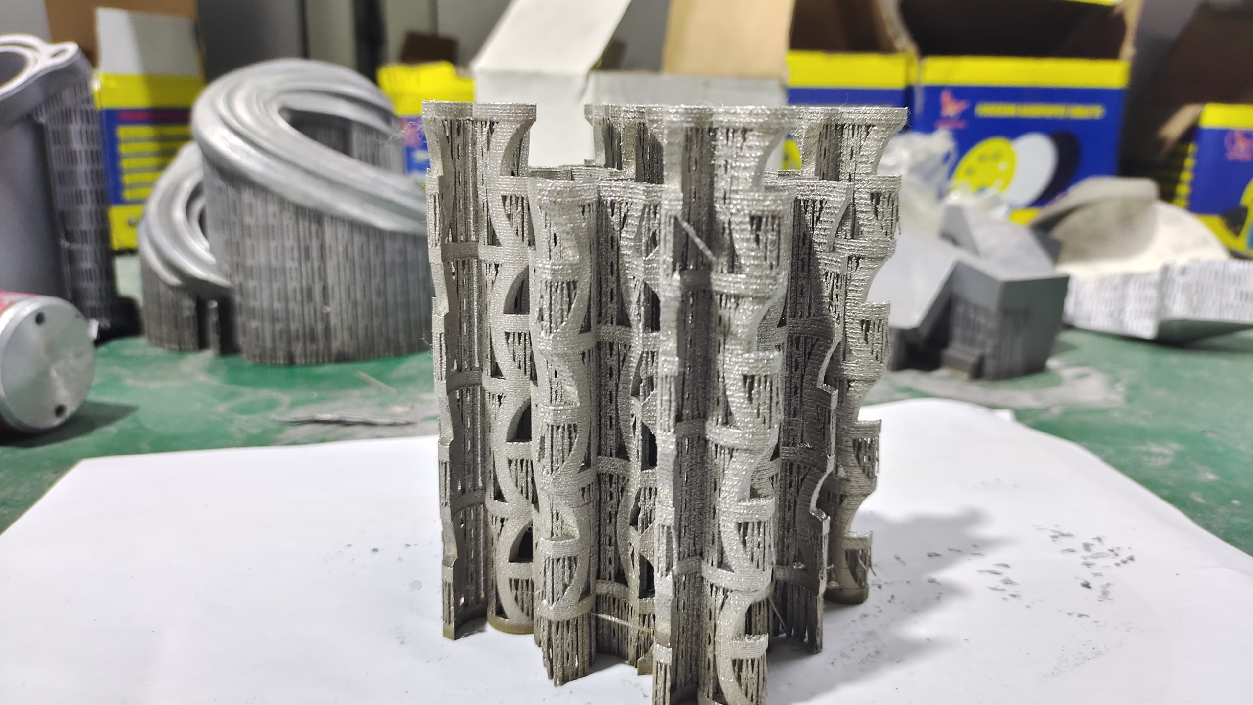
3d printing rock climbing parts makes sense when the shape is organic, when the batch is small, or when the internal geometry cannot be reached by a cutter. A hold with an undercut, a hollow bracket with internal ribs, or a one-off route feature for a competition wall all fall into that group. Print time is measured in hours, and a design change costs a new file instead of a new mold.
It makes less sense when the part is a flat plate with two holes and a 25 mm thickness. A mill will cut that in a fraction of the time, with a known grain structure and a repeatable finish. The same applies to anything that needs a threaded interface, a press-fit bearing seat, or a flatness callout under 0.05 mm across a wide face.
The practical split is this: print the shape, machine the interface. Many production braces are a printed body bonded or bolted to a machined insert that carries the thread. That keeps the custom geometry on the printed side and the tolerance-critical features on the machined side.
- 1Print itUndercuts, internal ribs, hollow shells, one-off competition shapes
- 2Machine itFlat plates, threaded bosses, bearing seats, tight flatness callouts
- 3Combine themPrinted body plus machined insert for the bolt interface
Material Choice: Grip Feel, Weight, and Wear
Material decides three things at once: how the surface feels to a hand, how much the part weighs on a wall panel, and how long it survives chalk, sweat, and shoe rubber. These pull in different directions, so the choice is always a compromise.
PLA is stiff and cheap and prints cleanly, but it creeps under sustained load and softens in a hot car or a sunlit wall. PETG is tougher and slightly flexible, which helps when the brace is thin, but it scratches and holds chalk in the scratches. ABS and ASA handle higher temperatures and take more impact, at the cost of a heated chamber and more warping. Nylon with carbon fiber is the strongest common filament for a bracket, though it drinks moisture and needs drying before a print.
For anything that carries a rated load or a person's weight, a polymer print is the wrong answer. Metal additive processes such as DMLS produce a dense part from alloys like 316L stainless, 17-4PH, or Ti-6Al-4V (TC4). Those parts can be machined afterward on the critical faces, which brings the bolt holes and the mounting face back into tolerance.
Surface texture is a separate decision from material. A printed surface can be bead blasted, tumbled, or brushed to a consistent feel. Laser marking holds a route number or a batch code, with a minimum character height of 1.5 mm. If the surface is a wear face, plan the finish before you print, because blasting a thin wall removes material from both sides.
- 1PLAStiff and cheap; creeps under load and softens in heat
- 2PETG, ABS, ASATougher and more heat resistant; harder to print cleanly
- 3Nylon plus carbon fiberStrong bracket material; needs drying and a hardened nozzle
- 4316L, 17-4PH, TC4Metal options for load-bearing braces; machinable after printing
Process and Material Comparison for Climbing Braces
Use this to narrow the field before you commit to a drawing.
| Option | Best for | Limit to watch |
|---|---|---|
| FDM, PLA or PETG | Gym volumes, prototype braces, low-load covers | Creep, heat softening, layer line wear |
| FDM, nylon plus CF | Thin brackets, tool-free prototypes | Moisture pickup, nozzle wear, cost |
| SLA or DLP resin | Smooth grip surfaces, display shapes | Brittle under impact, UV aging |
| DMLS, 316L or 17-4PH | Load-bearing brackets, thin metal arms | Cost per part, need for post-machining |
| DMLS, Ti-6Al-4V | Weight-critical braces, high strength | Material cost, tighter print parameters |
| CNC, 6061-T6 or 7075 | Flat plates, threaded bosses, inserts | Tool reach into deep undercuts |
| CNC, 316L stainless | Corrosion resistance at bolt interfaces | Longer cycle time than aluminum |
Load Path, Wall Fixing, and Failure Modes
A climbing brace fails in three common places. The first is the bolt hole, where a small bearing area crushes the surrounding material. The second is the transition between a thick mounting pad and a thin arm, which is where a printed part usually cracks. The third is the wall interface itself, which is often the weakest link and has nothing to do with the brace.
Design the hole first. Give each bolt a bearing area large enough to spread the load, add a washer face, and keep at least two diameters of material around the hole. In a printed polymer part, orient the layers so the load runs along the layers rather than pulling them apart. In a metal part, this matters less, but the build direction still affects the fatigue life of a thin arm.
The bracket-to-wall connection deserves the same attention. A T-nut in a plywood panel and a bolted steel frame behave differently under the same pull. A brace that is fine on a steel frame can pull a T-nut through a panel if the backing area is too small. If you are designing for a gym, ask what the panel thickness and the fixing pattern are before you finish the model.
Test the finished part the way it will be used. A static pull on a test rig tells you about the bolt interface. A repeated cycle tells you about the printed layers. Both are worth doing on the first article, and cheaper than finding the failure mode on a wall.
- 1Bolt holeEnlarge the bearing area and add a flat washer face
- 2Thin transitionAdd a fillet or a rib where the arm meets the pad
- 3Layer directionOrient printed layers so load runs along them
Machining and Finishing After the Print
A printed brace is rarely finished when it leaves the machine. The mounting face usually needs to be flat, the bolt holes need a true diameter, and the thread needs to be cut rather than printed. This is where a printed body meets a CNC operation.
Face the mounting pad on a mill to establish a flat reference, then drill and ream the bolt holes from that face. Machining to ±0.005 mm is normal for these features, and it costs far less than printing an entire metal brace to the same accuracy. If the brace needs a threaded insert, press or bond a machined insert into a printed pocket rather than cutting the thread into polymer.
Finishing follows the same logic. Anodizing, powder coating, and black oxide apply to metal braces. Bead blasting and tumbling work on both metal and polymer and give a consistent hand feel. Laser marking puts a batch code or a route number on the part, which helps when a gym tracks wear across a set of braces.
For a batch of one, print the body and machine the insert. For a run of a thousand, compare the printed route against a machined route on total cost, not on unit cost alone. Tooling, inspection, and finishing all count.
- 1Face firstEstablish the mounting face as the reference for every hole
- 2Machine the interfaceDrill, ream, and thread after printing
- 3Finish lastBlast, coat, or mark after the geometry is stable
Common Questions
Can a 3D printed climbing brace hold a climber's weight?
A polymer print is not a rated load-bearing part. Use it for volumes, covers, and prototypes.
For anything that carries a person, use a metal additive part such as 316L or 17-4PH, or a machined bracket, and test the first article under the real load.
Which is cheaper for a small batch, printing or CNC machining?
For one to twenty parts with organic geometry, printing usually wins because there is no tooling.
For flat plates and simple brackets, CNC machining is often cheaper per part and holds tighter tolerances on the mounting face.
How do printed layers affect grip and wear?
Layer lines give a directional texture that changes with print orientation and layer height.
On a wear face, the layers can flake or polish over time. Bead blasting or tumbling evens out the surface, and a machined insert should carry any sliding contact.
Can you print a brace and then machine the bolt holes?
Yes. Print the body with a machining allowance on the mounting face and undersized holes.
We face the pad, then drill and ream to final size, which brings the interface to ±0.005 mm.
What file format and information do you need for a quote?
Send a STEP file if the part has critical features, or an STL for a shape-only review.
Include the material, the quantity, the finish, and the load direction if the brace carries a pull. A DFM review comes back within 12 hours.
Do you sign an NDA for a new climbing product?
Yes. Uploads are handled as confidential, and a non-disclosure agreement is available on request.
We can start from a single prototype and scale to a 10,000+ part run with no minimum order quantity.
Send Us Your Brace Design
Upload a STEP file and get a DFM review, a material recommendation, and a quote within 12 hours.
12-hour quote100% inspectionNo minimum order quantityNDA on request









