
A Precision CNC Turn Mill Machining Center With Gear Hobbing Capability
This page explains what a precision CNC turn mill with an integrated hobbing unit actually does, which parts belong on it, and which ones do not. Engineers and machining buyers who must choose between one multi-tasking setup and a three-machine route will find the decision criteria here.
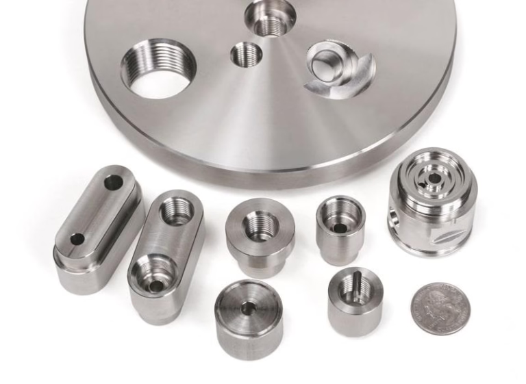
What changes when turning, milling and hobbing share one spindle
A turn-mill with a hobbing head is a lathe, a machining center and a gear cutter inside one enclosure, running off a single coordinate system.
How the three operations share one setup
A precision CNC turn mill starts life as a lathe. The main spindle turns the part, and a tool turret handles outside diameter turning, facing, boring and threading. What separates it from a plain lathe is the second turret or a B-axis head that carries live milling tools. That head drives end mills, drills and taps while the spindle holds the part or indexes it.
Add a hobbing unit and the machine gains a third function. The hob is a rotating cutter with helical gashes, and the spindle acts as a C-axis under closed-loop control. Hob rotation and workpiece rotation stay synchronized through the controller, so the cutter generates the involute flank tooth by tooth. No form tool, no separate gear machine.
The payoff is geometric. Turning, milling and hobbing all reference the same spindle centerline and the same zero point. Re-clamping a part on a second machine adds runout, and every new fixture adds its own stack of tolerances. On a turn-mill that stack mostly disappears.
Cycle time matters too, but not in the way people expect. Cutting time is often similar to the three-machine route. What shrinks is everything around the cut: queue time, transport, re-fixturing and the inspection that follows each move.
- 1C-axisProgrammable spindle orientation, required for hobbing and cross-drilling
- 2B-axis headTilts the milling spindle for angled features and hob access
- 3Bar feederLets a turned shaft run lights-out from bar stock
- 4Sub-spindlePicks up the part for back-end turning without a second setup
Which parts belong on a turn-mill with hobbing
The classic candidate is a shaft with a gear on it. Think of a drive pinion with a turned journal at each end, a keyway, a cross-drilled oil hole and a spur gear in the middle. Put that on a lathe, then a mill, then a gear hobbing machine and you have three fixtures and three chances to lose concentricity between the journal and the gear pitch circle.
Small gearboxes and actuator output shafts fit the same pattern. So do parts where the gear sits close to a shoulder or a bearing seat, because the relationship between the gear and that seat is what controls noise and wear in the assembly. Holding both in one setup keeps that relationship tight.
Medical and robotics work also shows up here. Drive trains in surgical instruments, imaging gantries and dental handpieces often need a small gear plus turned bearing surfaces in a part no bigger than a thumb. Re-fixturing a part that size is where scrap comes from.
There is a size limit worth naming. Our mill-turn centers handle work up to 4,000 mm in the longest axis, with common working envelopes of 750 × 1,150 × 550 mm and 600 × 600 × 600 mm. Parts far outside those envelopes go to a different route.
- 1Good fitShafts and hubs with turned features plus a gear or spline on the same axis
- 2Good fitParts where gear-to-bearing-seat concentricity drives assembly noise
- 3Poor fitSimple prismatic plates with no rotational features
- 4Poor fitVery large gear blanks beyond the machine envelope
Turn-mill with hobbing versus a three-machine route
Same part, two process routes. The differences below are the ones that usually decide the choice.
| Factor | Turn-mill + hobbing | Lathe, mill, gear machine |
|---|---|---|
| Setups | One | Three or more |
| Fixtures | One chuck or collet | One per machine |
| Concentricity | Set by the spindle | Accumulates per re-clamp |
| Queue time | Removed | Added at each machine |
| In-process handling | None between ops | Transport and re-fixturing |
| Deburring access | Same setup as cutting | Often a separate manual step |
| Best for | Complex rotational parts | Simple parts, high volume per op |
| Tooling cost | Higher, more live tools | Lower per machine |
| Setup time | Longer first article | Shorter per operation |
Tolerances, surface finish and how we hold them
GreatLight works to ±0.005 mm (±0.0002 in) on turned and milled features. That number only means something when the datum is stable, which is the real argument for single-setup work. When the gear, the journal and the bearing seat are cut without the part leaving the chuck, the tolerance band applies across all of them at once.
Surface finish depends on the operation. Turned and milled surfaces land at Ra 1.6–3.2 μm as machined, Ra 0.8–1.6 μm on our high-finish passes, and Ra 0.2–0.8 μm where a fine finish is specified. Gear flanks are a separate conversation: hobbed flanks come off the cutter with a defined profile, and the finish depends on hob condition, feed and material.
Materials behave differently on a mill-turn. Aluminium 6061 and 7075 cut fast and hold size well. Stainless 303 and 17-4PH work but push tool wear. Titanium TC4 and Inconel need lower cutting speeds and more attention to heat. Brass C36000 hobs cleanly and is often the easiest gear material we run.
Inspection runs across the whole batch. We check raw material on arrival, monitor dimensions in process, and inspect before shipment. Reports are available on request, including gear-specific measurements when the drawing calls for them.
- 1Tolerance±0.005 mm on turned and milled features
- 2Fine finishRa 0.2–0.8 μm where specified
- 3Standard finishRa 1.6–3.2 μm as machined
- 4Inspection100% before shipment, reports on request
When a turn-mill is the wrong call
Multi-tasking machines are not free. Hourly rates run above a single-purpose lathe, and programming takes longer because the engineer has to think about chuck jaw clearance, tool reach and the order of operations across two turrets. For a simple turned bushing with no milling and no gear, that overhead buys nothing.
Gear geometry has limits too. Hobbing generates involute teeth well, but it cannot cut a shoulder-adjacent gear with no runout clearance, and it will not produce internal teeth. Internal gears, face gears and some worms go to shaping, broaching or grinding instead.
Hardened gears are another boundary. If the drawing calls for teeth harder than roughly 45 HRC, hobbing in the soft state followed by grinding is usually the practical route, and that grinding step sits outside the turn-mill.
Finally, consider volume. For 50,000 identical simple parts, dedicated machines with short cycles usually win. The turn-mill earns its place when the part is complex, the batch is moderate, or the geometry makes re-fixturing risky.
Machines, lead time and how to start
GreatLight has been machining since 2011 and runs 127 high-precision CNC machines across three wholly-owned plants covering 7,600 m² in Dongguan, with a Singapore facility at No.3 Joo Koon Circle. The fleet includes 16 mill-turn centers, 16 simultaneous 5-axis machining centers, 12 four-axis mills and 27 three-axis machines.
Quotation and a free DFM analysis come back within 12 hours of receiving drawings. Production can start within 24 hours, and parts typically ship in 3–5 days. There is no minimum order quantity, so a single prototype and a 10,000-part run go through the same process.
Uploads stay confidential, and we sign an NDA on request. We hold ISO 9001:2015, IATF 16949:2016, ISO 13485:2016 and ISO 27001:2022. If you are weighing a turn-mill against a multi-machine route for a specific part, send the drawing and let us tell you which one we would quote.
Common questions
Can a turn-mill hob both a gear and a spline on the same part?
Yes, if the spline is an involute form and the hob can reach it. Straight-sided splines are usually milled with a form cutter on the same machine instead.
The practical limit is tool access. If two geared features sit on opposite sides of a shoulder, the hob may not clear the shoulder on both.
What gear module or pitch range is realistic?
Hobbing on a mill-turn covers the range you would expect from a small gear hobbing machine, from fine instrument gears up to coarser drive gears.
Send the module, tooth count and face width with the drawing. We confirm reach and cycle time before quoting rather than after.
Does one setup really remove all concentricity error?
No, but it removes the error that comes from re-clamping. Residual error comes from spindle runout and thermal drift.
In practice, single-setup work holds the gear pitch circle and the bearing seat to the same tolerance band, which is the part that matters in an assembly.
Which materials give the best hob life?
Brass C36000 and aluminium 6061 hob cleanly with long tool life. Low-carbon steel like 1045 sits in the middle.
Stainless 17-4PH, titanium TC4 and Inconel wear hobs faster and usually need a fresh cutter or a resharp before a long run.
How do I know if my part should be quoted on a mill-turn?
Count the machines it would need. If it takes a lathe plus a mill plus a gear machine, it is a candidate.
If it needs a lathe only, or if the gear can be bought as a separate pressed or sintered part, a simpler route is usually cheaper.
Can you machine a prototype before we commit to a run?
Yes. There is no minimum order quantity, so a single piece can go through the same setup as a production run.
That first article is often the cheapest way to find out whether a design is hob-friendly before tooling is committed.
Send a drawing and get a route recommendation
We review your part, confirm whether a precision CNC turn mill with hobbing is the right process, and return a quote with free DFM analysis within 12 hours.
12-hour quote100% inspectionNDA on request









