
Advanced CNC Plastic Machining Services
Cutting plastic is not cutting aluminum with a different feed rate. This page explains which polymers machine cleanly, what tolerance you can hold, and where the process stops making sense. Written for design engineers and sourcing teams comparing quotes.
What Changes When the Workpiece Is Plastic
Same machines, different physics. Thermal expansion, chip welding and part flex decide the result more than spindle speed does.
Why Plastic Behaves Differently at the Spindle
The cutting strategy changes the moment the workpiece is polymer instead of metal, even on the same 3-axis, 4-axis and 5-axis centers. Plastics conduct heat poorly. Nearly all of the energy your cutter puts into the chip stays near the edge, so the material softens, smears and welds back onto the flute. A tool that runs cool in 6061 will melt its way through POM.
Chip evacuation matters more than depth of cut. Plastic chips are light, springy and prone to static, so they pack into flutes and recut. We favor two and three flute cutters in polished carbide with high helix angles, run aggressive feed per tooth, and use air blast rather than flood coolant on most polymers. Coolant on hygroscopic grades like PA can introduce moisture and dimensional drift after machining.
Clamping is the other trap. Plastics flex under vise pressure and spring back after you unclamp, so a bore that measured on size at the machine can be 0.05 mm out once it relaxes. We rough, rest, then finish with light radial engagement. Soft jaws, vacuum fixturing and sacrificial backing plates keep the part supported without crushing it.
- 1HeatPoor conductivity keeps heat at the cutting edge. Air blast beats flood coolant.
- 2ChipsLight, static-prone chips recut easily. Use sharp polished flutes and strong evacuation.
- 3ClampingVise pressure deforms plastic. Rough, release, then take light finishing passes.
Which Polymers Machine Well, and Which Do Not
Not every plastic is a good candidate. Semi-crystalline grades such as POM, PEEK and PA machine to a clean edge with predictable chips. Amorphous grades like PC and PMMA cut cleanly too, but they are notch sensitive and more prone to crazing around threads and sharp internal corners. Glass filled and carbon filled compounds wear tools fast and need diamond coated or PCD cutters to hold size across a run.
Soft, low modulus materials are the hard cases. LDPE, HDPE and soft PP deflect away from the cutter instead of shearing. You can still machine them, but holding ±0.005 mm across a long thin wall is unrealistic. We typically tell engineers to design thicker sections, add radii, and accept a looser tolerance band on these grades.
PTFE and UHMW bring a third problem: creep. A part that measures correctly on the CMM may relax over days under its own weight or clamp load. If your assembly depends on a press fit in PTFE, plan for a wider interference range or move to a filled grade.
- 1GoodPOM, PEEK, PA, PC, PMMA, ABS. Sharp edges, stable chips, repeatable size.
- 2DemandingFilled grades wear tools and need PCD or diamond coating for production runs.
- 3DifficultLDPE, PP, PTFE, UHMW deflect and creep. Loosen tolerance expectations.
Machining Behavior by Common Plastic
Practical starting points, not hard limits. Wall thickness and feature geometry still govern the result.
| Material | Machinability | Typical finish | Watch out for |
|---|---|---|---|
| POM (Delrin) | Excellent | Ra 0.8–1.6 μm | Internal stress relief after roughing |
| PEEK | Very good | Ra 0.8–1.6 μm | Abrasive; keep feeds high, heat low |
| PA (Nylon) | Good | Ra 1.6–3.2 μm | Moisture uptake changes dimensions |
| PC | Good | Ra 0.8–1.6 μm | Notch sensitive, crazes near sharp corners |
| PMMA (Acrylic) | Good | Ra 0.2–0.8 μm | Chip welding and edge chipping |
| ABS | Very good | Ra 1.6–3.2 μm | Low stiffness on thin ribs |
| Carbon fibre composite | Fair | Ra 1.6–3.2 μm | Tool wear, delamination at exit |
| HDPE / PP | Fair | Ra 1.6–3.2 μm | Deflection and burr on soft edges |
What Tolerance You Can Realistically Hold
On rigid, filled or semi-crystalline parts with sensible wall thickness, our advanced CNC plastic machining holds ±0.005 mm on critical features and holds it across the run. That number assumes a short feature, a supported workpiece and a stable shop temperature. It is not a blanket tolerance for every dimension on the drawing.
Long thin parts are the exception. A 300 mm unsupported plastic wall will move more than 0.1 mm from thermal and stress effects alone, regardless of how good the machine is. If the drawing demands tight tolerance across that span, the design usually needs a rib, a thicker section or a different material. Surface finish follows the same logic: Ra 0.8–1.6 μm is routine, Ra 0.2–0.8 μm is achievable on faces you can reach with a finishing pass and a rigid setup.
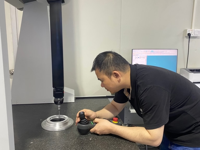
Inspection is where this gets settled. We check incoming stock, monitor dimensions during the run, and inspect 100% before shipment. Reports are available on request. For plastic parts, we also let the part stabilize before final measurement rather than measuring hot off the machine.
- 1Rigid features±0.005 mm is achievable on supported, short, thick-sectioned geometry.
- 2Long thin wallsExpect 0.1 mm or worse. Add ribs or thicken the section.
- 3FinishRa 0.8–1.6 μm standard; Ra 0.2–0.8 μm on accessible finishing faces.
When Plastic Is the Right Answer, and When It Is Not
Plastic wins when you need electrical insulation, chemical resistance, low weight or low inertia. It also wins on small quantities of complex geometry, where the tooling cost of injection molding cannot be justified. We run prototypes and low volume production with no minimum order quantity, from one part to 10,000+ piece runs, so the crossover point is decided by your volume, not by our setup.
Plastic loses on stiffness and thermal stability. If a bracket must resist a 200 N load without deflecting more than 0.2 mm, or if the part lives at 150 °C, an aluminum or stainless version is usually the better call. PEEK and filled grades close part of that gap, but they cost more than 6061 per kilogram and still will not match metal modulus.
A third case is wear. Sliding surfaces in unfilled plastic wear quickly and generate debris. If the part is a bearing surface or a cam follower, expect to add a metal insert, switch to a bronze filled compound, or machine the feature in metal and overmold or assemble it into the plastic housing.
How We Set Up Plastic Jobs
Process planning starts before the toolpath. We look at wall thickness, aspect ratio and where the part needs to be held. Thin walls get support from the back. Deep pockets get smaller stepdowns and a finishing pass with reduced radial engagement so the wall does not push away from the cutter.
Deburring is manual on most plastic parts, and it matters more than on metal. A raised edge on a plastic housing will not sit flat, and a sharp corner is a crack starter under vibration. We control edges with light chamfers and radius tools rather than scraping, which smears the surface.
For multi-operation parts, we keep the whole chain in house. Machining, turning, finishing and assembly run under the same roof, so the part is not re-clamped and re-datumed between vendors. That is where size drifts on plastic. Combined with 127 high precision CNC machines, 16 simultaneous 5-axis centers and a 4,000 mm maximum processing size, we can take large panels and complex housings without splitting the job.
Every upload is treated as confidential. An NDA is available on request, and files are not shared outside the project team.
- 1SetupSupport thin walls, reduce radial engagement on finishing passes.
- 2EdgesChamfer and radius instead of scraping. Sharp corners crack under vibration.
- 3One roofMachining and finishing in house avoids re-datum drift on plastic parts.
Questions Engineers Ask Before Ordering
Can you hold ±0.005 mm on POM or PEEK?
Yes, on supported features with reasonable wall thickness. The tolerance depends on the geometry, not only the material. A 20 mm bore in a thick section is realistic at ±0.005 mm. A 300 mm unsupported wall is not.
Send the drawing with the critical dimensions marked. We will tell you which ones we can hold and which ones need a design change.
Do you machine glass filled or carbon filled plastics?
Yes. Filled compounds are abrasive and wear carbide quickly, so we use diamond coated or PCD tooling on production runs and change cutters on a schedule rather than waiting for size to drift.
Filled grades also tend to chip at the exit edge. We plan the toolpath to exit into sacrificial material where the geometry allows.
What is the minimum order quantity?
There is no minimum. We run from a single prototype to 10,000+ part runs. Prototype and production parts come off the same machines, so the process does not change between them.
How fast can I get parts?
Quotation and a free DFM analysis come back within 12 hours. Production can start within 24 hours of approval, and parts typically ship in 3–5 days.
Complex multi-operation parts or large panels take longer. We will give you a real date in the quote, not a best case.
Do you provide inspection reports for plastic parts?
Yes, on request. Every part is inspected 100% before shipment, with incoming material checks, in-process monitoring and final inspection. For plastic we let the part stabilize before final measurement.
First article inspection reports and dimensional data can be included with the shipment.
What surface finishes can you apply to plastic?
Bead blasting, tumbling, brushing and polishing are all suitable for plastics. Laser marking and engraving work on most grades, with a minimum character height of 1.5 mm.
Plating and anodizing are metal processes and do not apply to polymer parts.
Send a Drawing, Get a Straight Answer
Upload your part and we will return a quote plus a free DFM analysis within 12 hours, including which tolerances are realistic in your chosen polymer.
12-hour quote100% inspectionNo MOQNDA on request









