
Aluminum CNC ink protection for machined parts
This page explains how ink, paint and marking fluids behave on machined aluminum, and which coating or masking route keeps them from bonding. It is written for engineers and buyers specifying printed, pad-printed or laser-marked aluminum components. After reading it you can pick a surface treatment and a masking plan for your part geometry, and know when aluminum is the wrong substrate.
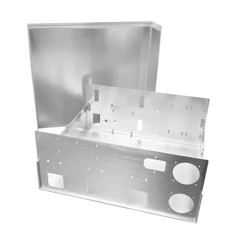
What ink protection actually means on a CNC part
Ink protection is a surface decision made before the first cut, not a step added at the end.
Why ink sticks to aluminum and where it hurts
Machined aluminum is rarely uniform on the surface. Milling leaves a directional texture, deburring leaves microscopic scratches, and cutting fluid residue sits in those valleys. Ink and paint flow into that texture and key mechanically to the metal. Once cured, the bond is stronger than the surface layer holding it, so removal pulls up aluminum with it.
Breaking that bond is the job of ink protection. Three routes do most of the work on production parts: an anodized layer that seals the pores, a masking film that keeps ink off functional faces, and a controlled surface finish that gives ink nothing to grab. Pick wrong and you get smeared date codes, peeling pad prints, or paint that lifts during cleaning.
Volume matters here. A single prototype can be wiped clean by hand. A 10,000-part run cannot, so the surface spec has to be repeatable from the first part to the last.
Anodizing, chromate and plating: which layer blocks ink
Anodizing grows an oxide layer out of the aluminum itself, so it does not chip off at an edge like a painted film. Type II clear anodizing gives a thin, hard, non-conductive skin that most solvent-based inks will not wet out on. Hardcoat anodizing goes thicker and is the usual choice for wear faces that also see ink.
Conductive anodizing exists for a reason: some assemblies need the ink protection and a ground path on the same part. It keeps selected areas electrically live while the rest of the surface stays sealed.
Electroless nickel and zinc plating work when the part also needs wear or corrosion resistance beyond what an oxide layer gives. Both change dimensions, so the drawing has to state whether plating is pre- or post-machining. Laser marking on plated aluminum is usually crisp because the layer is uniform.
Powder coating is a different animal. It is thick, so it hides machined detail and cannot hold a ±0.005 mm tolerance on a coated face. Keep powder off any surface that mates, seals, or carries a print.
Surface options for aluminum CNC ink protection
Match the layer to the function of the face, not to the whole part.
| Treatment | Typical thickness | Ink behavior | Use when |
|---|---|---|---|
| Type II clear anodize | 5–25 μm | Ink beads; wipes clean | Housings, panels, cosmetic faces |
| Hardcoat anodize | 25–50 μm | Ink resistant, wear resistant | Sliding or handling faces |
| Conductive anodize | 5–25 μm | Ink resistant, masked areas live | Ground path plus sealed body |
| Electroless nickel | 10–25 μm | Uniform, laser marks well | Wear plus corrosion duty |
| Bead blast + clear anodize | Substrate only | Matte, even ink laydown | Pad printing at volume |
| Powder coat | 60–120 μm | Ink sits on top, can lift | Non-critical covers only |
Masking plans that survive anodizing and plating
Every coated part has faces that must stay bare: threads, dowel holes, sealing lands, ground pads, and any surface that will be welded later. Masking is how you keep them that way, and it is planned at the CAM stage, not after the parts come off the machine.
Masking tape works for flat areas and shallow recesses. Plugs and silicone caps handle threaded holes and bores. For tight-tolerance bores, a machined allowance is often cleaner than a plug, because the anodize growth can be removed in a light finish pass after coating.
The failure mode we see most is a mask line that lands on a sealing face. Anodize grows outward and slightly undercuts the tape edge. That step is a few micrometres tall, but it is enough to break a face seal. Move the mask line onto a non-functional step, or machine the land after coating.
Laser marking is the other half of the plan. On anodized aluminum, a fiber laser burns through the oxide and leaves a high-contrast mark without ink at all. Minimum character height is 1.5 mm. Below that, mark legibility drops and you should consider a printed label instead.
Part features that decide the ink protection route
Thin walls behave badly under coating. A 0.8 mm aluminum wall can warp during hardcoat anodize because the oxide layer grows on both sides and builds internal stress. If the wall is thin, we usually steer the design to Type II anodize or a plated finish.
Deep pockets trap ink and trap mask residue. A pocket deeper than three times its width is hard to mask cleanly and hard to clean after. Where the pocket is cosmetic only, a bead-blasted and anodized finish hides handling marks better than a bright machined finish.
Threads are the classic conflict. Anodize adds roughly half its thickness to each flank, which changes pitch diameter and can make a nut bind. We normally mask threads, or cut them 0.02–0.05 mm oversize before coating, then chase them after. State which one you want on the drawing.
Large parts bring a different problem. On a 4,000 mm part, coating thickness varies across the length, so ink adhesion can look different at the two ends. If the whole face must print evenly, break the job into smaller printed sub-panels rather than coating one long extrusion.
Common questions on aluminum CNC ink protection
Does anodizing always stop ink from sticking?
No. A sealed Type II anodized surface resists most solvent inks, but some UV-cure and epoxy inks still wet out on a matte finish. If the ink must stay, we test the exact ink and surface combination on a coupon before the run.
Hardcoat anodize is more forgiving because the thicker oxide is less porous. Conductive anodize behaves like Type II on the sealed areas.
How much does the coating change my dimensions?
Anodize grows into the part and outward. A Type II layer of 5–25 μm adds roughly half that to each coated face. Hardcoat at 25–50 μm adds more.
Plated layers like electroless nickel also build outward. If a face carries ±0.005 mm, tell us whether the tolerance applies before or after coating, and we will set the pre-machining size accordingly.
Can you laser mark instead of printing ink?
Yes, on anodized and plated aluminum a fiber laser gives a permanent, ink-free mark. Minimum character height is 1.5 mm.
For very small text or barcodes, pad printing or a label is often more readable. Both can be combined with an anodized base if the ink is specified for that surface.
What surface finish should I specify for pad printing?
Ra 0.8–1.6 μm gives a consistent matte surface that holds a pad print evenly. A mirror polish at Ra 0.2–0.8 μm looks good but lets ink slide during transfer.
As-machined Ra 1.6–3.2 μm can work, but the tool marks show through thin ink. Bead blasting before anodize evens that out.
Which aluminum alloys are a poor fit for ink protection?
High-silicon die casting alloys such as ADC12 anodize unevenly because the silicon phase does not oxidize with the aluminum. The result is a mottled surface and patchy ink adhesion.
For printed faces, 6061, 6061-T6, 6082 and 7075 give the most predictable anodize. 5052 and 5083 are fine for sheet metal covers that only need corrosion protection.
Do you handle masking and coating in one order?
Yes. Masking, anodizing, plating, bead blasting and laser marking run as post-processing steps on the same order, so the part is machined, masked, coated and marked without changing suppliers.
Uploads are secure and confidential, and an NDA is available on request.
Send your drawing and we will propose the surface route
Include the cosmetic faces, the functional faces and the ink or marking method, and our engineers will return a quotation with a free DFM analysis within 12 hours.
12-hour quote100% inspectionNo minimum order quantity









