
AM CNC Machining: What It Is and When to Use It
This page explains what AM CNC machining covers, how the cutting side of the shop is set up, and which part features decide the process. It is written for design engineers and sourcing engineers who need to pick a route before drawing release. After reading, you should be able to say whether a part belongs on a 3-axis mill, a 5-axis center, or a printer.
How to read this page
Four sections: what the term means in a job shop, machine and capacity limits, design rules that decide pass or fail, and the cases where you should not cut metal at all.
What AM CNC machining actually means
The letters usually stand for additive manufacturing, and the phrase is used in two ways. Some buyers mean a hybrid route: print a near-net shape, then finish the critical faces on a CNC. Others use it loosely for any precision CNC work on small-batch parts. At GreatLight we do both, and the difference matters for your drawing.
In the hybrid route, a metal AM blank arrives with 0.5–2 mm of stock on the faces that need to hold tolerance. The machinist faces, bores and threads those features. Internal channels printed into the part stay as printed, so their surface finish is set by the printer, not by the cutter. If a channel needs Ra 0.8 μm, the hybrid route will not deliver it without extra work.
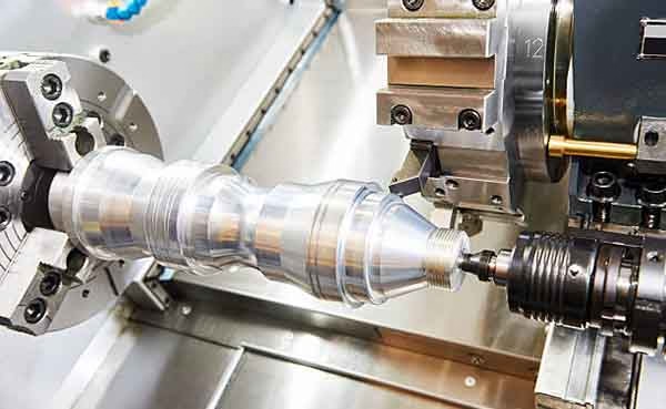
Pure subtractive work is still the default for most parts. A block of 6061 or 17-4PH goes onto a mill, and every surface is cut. You get tight control of flatness, bore roundness and thread fit. You also get a paper trail: material cert, in-process checks, final inspection report.
The practical question is not which label is better. It is which features on your part need to be cut, and which ones can be grown.
Machines, envelope and realistic limits
GreatLight runs 127 high-precision CNC machines across three wholly-owned plants in Dongguan and one in Singapore. The five-axis side has 16 simultaneous 5-axis machining centers, plus 12 four-axis mills, 27 three-axis machines and 16 mill-turn centers. That mix lets us route a job to the machine that fits it rather than forcing every part onto the largest one.
Envelope is a common sticking point. Our largest travel is 4,000 × 400 × 150 mm, which suits long extrusions, rails and structural beams. Medium travels cover 750 × 1,150 × 550 mm and 600 × 600 × 600 mm, the range where most automotive and industrial housings sit. Compact machines at 500 × 500 × 450 mm and 500 × 310 × 200 mm handle small, high-repeat parts and give better tool access on fine features.
A Ø400 mm rotary table covers 4-axis work: shafts with cross-drilled holes, parts with features on four sides, and anything where one setup saves a re-fixture. Every extra setup adds stack-up error. On a part with a 0.02 mm true position callout, cutting four faces in one 4-axis setup is usually safer than three separate 3-axis ops.
Repeatability is what buyers test. We hold ±0.005 mm (0.0002 in) on qualifying features, and the historical qualification rate is 99.99%. Those numbers depend on geometry. A 200 mm long bore is a different problem from a 20 mm one.
- 1Long parts4,000 × 400 × 150 mm travel; watch deflection at the far end.
- 2Boxy housings600 × 600 × 600 mm class machines keep five faces in one setup.
- 3Shafts and cross-holesØ400 mm rotary table removes a second op.
- 4Fine detailCompact 500 mm machines give shorter tools and less chatter.
Picking the right machine class
Match the part to the envelope before you match it to the tolerance.
| Part type | Best machine | Why |
|---|---|---|
| Long rail or beam | 5-axis, 4,000 mm travel | One setup along the full length |
| Housing, 5 faces | 5-axis, 600 mm cube | No re-fixture, less stack-up |
| Shaft with cross-holes | 4-axis + Ø400 mm table | Rotary indexing holds position |
| Thin plate, many holes | 3-axis, 500 mm class | Fast tool changes, low cost |
| Turned bushing | Mill-turn center | Turning and milling in one cycle |
| Prototype, 1 pc | 3-axis or 5-axis | No tooling cost, days not weeks |
Materials and what they do to your design
Aluminum is the workhorse. We stock 6061, 6061-T6, 2024, 5052, 5083, 6063, 6082, 7075 and ADC12. 6061-T6 machines cleanly and anodizes well, which is why it covers most brackets and enclosures. 7075 gives higher strength but is less forgiving on thin walls; below about 1 mm wall thickness it starts to move during cutting. 2024 is strong and fatigue-resistant, though it needs a coating because bare 2024 corrodes.
Stainless covers 303, 304, 316, 316L, 420, 430, 431, 440C and 17-4PH (SUS630). 303 is the free-machining grade, good for bushings and fittings where corrosion demand is moderate. 316L is the pick for medical and marine parts. 17-4PH can be aged to high strength after machining, but plan the heat treat before you finalize tolerances, since aging moves dimensions slightly.
Steel grades include 1018, 1045, 4130, 4140, 4340, A36 and tool steel. 4140 and 4340 are common for shafts and load-bearing parts. Copper and brass cover C101, C103, C110, beryllium copper, C27400, C28000 and C36000; C36000 is the easy one to cut, beryllium copper is not, and it needs coolant control.
For high-temperature and weight-critical work we machine TA1, TA2, TC4 (Ti-6Al-4V), Inconel and magnesium AZ31B / AZ91D. Titanium and Inconel cut slowly and generate heat at the edge, so tool life drives cost more than cycle time does. Plastics include ABS, PC, PMMA, POM, PA, PEEK, PP, HDPE and carbon fibre. POM holds tolerance well; PEEK is dimensionally stable at temperature but expensive; carbon fibre eats cutters and needs diamond tooling for clean edges.
Material quick reference
| Material | Typical use | Watch out for |
|---|---|---|
| 6061-T6 | Brackets, enclosures | Anodize color shifts by lot |
| 7075 | Aerospace structure | Thin walls distort after cutting |
| 303 stainless | Bushings, fittings | Lower corrosion resistance |
| 316L | Medical, marine | Gummy chips, slower feeds |
| 17-4PH | High-strength shafts | Aging moves dimensions |
| Ti-6Al-4V | Weight-critical parts | Heat at the cutting edge |
| POM | Insulators, gears | Low melting point, keep coolant on |
| PEEK | High-temp insulators | High cost per kilogram |
Features that decide pass or fail
Tolerance is a budget, not a wish. A ±0.005 mm callout on a 6 mm bore is routine. The same callout on a 300 mm bore with a 0.5 mm wall is not, because thermal drift and clamping force move the part more than the cutter does. Spend the tight tolerance on the features that mate. Leave the rest at ±0.1 mm and the price drops.
Deep pockets and tall ribs are the two features that cause most rework. A pocket deeper than four times its width needs a long, thin tool, and long tools chatter. If you can open the corner radius to at least one third of the pocket depth, the machinist can use a stiffer cutter and hold the floor flat. Ribs thinner than 1 mm in aluminum or 0.8 mm in steel tend to spring back after the vise opens.
Surface finish follows the same logic. As-machined Ra 1.6–3.2 μm covers most functional faces. Ra 0.8–1.6 μm is the normal callout for sealing faces and bearing bores. Ra 0.2–0.8 μm needs a finishing pass with a small stepover, or a secondary operation such as lapping or polishing. Specify the finish only where it does work; a mirror finish on a non-contact face adds cost with no benefit.
Threads deserve a line of their own. We cut threads from M1.6 upward, and the minimum laser-marked character height is 1.5 mm. If your marking is smaller than that, it will not read after anodizing. Tell us the marking requirement early, because it can change the order of operations.
- 1Corner radiusAt least 1/3 of pocket depth keeps tools rigid.
- 2Wall thickness1 mm aluminum, 0.8 mm steel is the practical floor.
- 3Tolerance placementTight only on mating features, loose elsewhere.
- 4Marking size1.5 mm minimum character height for laser marking.
When not to choose CNC
CNC is the wrong route when the geometry is mostly internal and organic. Lattice structures, conformal cooling channels and hollow sections with no straight tool access cannot be cut. If those features carry the function, print the part and machine only the interface faces.
It is also the wrong route at very high volume in a single simple shape. A bracket that will run 200,000 pieces a year is usually cheaper as a die casting or a stamping, with CNC used only on the critical bore. We run die casting and sheet metal in-house, so we can tell you where the crossover sits for your part instead of guessing.
The third case is a part that is mostly a surface. Large, smooth, sculpted panels with no tight features are often faster to form than to cut. Cutting them means removing a lot of material slowly, and the finish still needs hand work.
Everything else, from one prototype to a 10,000-piece run, fits the cutting route. There is no minimum order quantity, and a one-piece order goes through the same inspection as a production batch.
Questions engineers ask next
How do you decide between 3-axis, 4-axis and 5-axis for my part?
We look at how many faces carry features and how tight the positional callouts are. If everything is on one face, a 3-axis machine is cheaper and just as accurate. Features on four sides usually go to a 4-axis with the Ø400 mm rotary table. Compound angles or features that need the tool to reach under a lip go to a 5-axis center.
The deciding number is often setup count. Each re-fixture adds error. When two extra setups would put a true position callout at risk, the 5-axis route is the safer one even if the cycle time is longer.
What tolerance and finish can you hold in production?
We hold ±0.005 mm (0.0002 in) on qualifying features. Standard as-machined finish is Ra 1.6–3.2 μm. For sealing faces and bearing bores we work to Ra 0.8–1.6 μm, and Ra 0.2–0.8 μm is available with a finishing pass or a secondary operation.
The limit depends on geometry more than on the machine. Long, thin parts move; short, rigid parts do not. Send the drawing and we will tell you which callouts are realistic.
How fast can I get parts?
Quotation and a free DFM analysis come back within 12 hours. Production can start within 24 hours of a released order, and parts typically ship in 3–5 days. Our historical late-delivery probability is below 2%.
Timing depends on material availability and finish. Anodizing and plating add days because they run outside the cutting cycle.
Which certifications apply to my project?
We hold ISO 9001:2015, IATF 16949:2016, ISO 13485:2016 and ISO 27001:2022. Automotive work runs under IATF 16949, medical hardware under ISO 13485, and data handling under ISO 27001.
Inspection is 100% before shipment: raw material check, in-process monitoring and final inspection. Reports are available on request.
Can you machine printed or cast blanks?
Yes. We regularly finish metal AM blanks, die castings and vacuum castings on CNC. The critical faces get cut to tolerance while the near-net shape saves material.
Send the blank drawing with the finished drawing. We need to know how much stock is on each face and whether the blank has been stress-relieved.
What post-processing do you offer?
Anodizing in clear, color, hardcoat and conductive; electroless nickel, zinc, silver and gold plating; powder coating and black oxide; bead blasting, tumbling, brushing and polishing; laser marking and engraving down to 1.5 mm character height.
Pick finishes before quoting. Some coatings add thickness that changes a press fit by more than the machining tolerance.
Send a drawing, get a process answer
Upload your files and we will return a quotation with a free DFM analysis within 12 hours. Uploads stay confidential, and an NDA is available on request.
12-hour quote100% inspectionNo minimum order quantity









