
Bothered by turning internal holes? How to machine an interior bore in one setup
Internal turning is where most lathe problems show up: chatter, taper, poor finish and chips that will not leave. This guide is for engineers and machinists who need a straight answer on tooling, parameters and setup. Read it and you can decide whether a bore belongs on the lathe, the mill, or a mill-turn center.
What actually goes wrong inside a bore
Almost every internal turning problem traces back to one of four things: tool overhang, chip flow, heat, or the way the part is held.
Internal turning: what it is and where the difficulty comes from
Internal turning, often called boring or reaming depending on the tool and the intent, enlarges an existing hole or finishes the inside surface of a hollow part. The cutting action is the same as external turning. The conditions are not. A boring bar has to reach into the part, so the tool is long and thin relative to the forces on it. That single fact drives deflection, chatter and taper.
On the outside of a shaft, the workpiece supports the cut. Inside a bore, the bar is the weakest element in the loop. A Ø20 mm boring bar hanging 120 mm out of the holder will deflect far more than a Ø20 mm end mill held in a collet 30 mm from the spindle. If you are bothered by turning internal features that never come out round or on size, measure the bar overhang before you change a single speed or feed.
Bore diameter sets the limit too. Below roughly Ø6 mm, standard boring bars run out of stiffness and chip room, and the work usually moves to drilling, reaming or helical milling. Above Ø200 mm, the part itself often becomes the flexible element and the setup has to change.
Most of the problems people bring to us are not exotic. They are long overhangs, chips packed in the bottom of a blind bore, and coolant that never reaches the cutting edge.
- 1Overhang ruleKeep bar overhang under 4× bar diameter where the geometry allows it.
- 2Blind boresLeave chip clearance at the bottom or switch to a through-coolant bar.
- 3Thin wallsReduce radial depth and expect the wall to spring back after the cut.
- 4Deep holesPast about 8:1 depth-to-diameter, plan on a different process.
Choosing a boring bar: steel, carbide, or damped
A steel shank bar is fine for short bores and light finishing passes. It is cheap, forgiving, and easy to shim. The moment overhang climbs past about 4× diameter, steel starts to sing and the surface finish goes with it. Carbide shank bars are roughly three times stiffer than steel at the same diameter, which is why they take over in the 4:1 to 6:1 range.
Tuned or damped bars carry an internal mass tuned to cancel the dominant vibration mode. They cost more and they have a narrow working window, but they are the only practical answer for deep, small-diameter bores where a solid bar chatters no matter what you do with speeds and feeds. For a Ø25 mm bore at 200 mm depth, a damped bar is not a luxury.
Insert geometry matters as much as the shank. Positive rake, sharp edges and a small nose radius reduce cutting force, which matters when the bar is already flexing. A large nose radius spreads the load and leaves a better finish on stable setups, but it pushes the bar harder. On a long overhang, go small.
Coolant delivery is part of tool selection, not an afterthought. Through-tool coolant at 70–100 bar clears chips from blind bores and cools the edge where it counts. Flood coolant from the outside rarely reaches the tip of a bar 150 mm inside a part.
- 1Steel shankShort bores, light finishing, low volume.
- 2Carbide shankThe default for 4:1 to 6:1 overhang.
- 3Damped barDeep or small bores where chatter will not stop.
- 4Through coolantBlind bores and any cut deeper than 3× diameter.
Bore size against practical process choice
Use this as a starting filter, not a rulebook. Part geometry and wall thickness can move a job either way.
| Bore range | Typical process | Watch out for |
|---|---|---|
| Under Ø3 mm | Drilling, then reaming | Bar stiffness is gone; chip jam is common |
| Ø3–6 mm | Drill + ream, or helical milling | Runout and tool breakage on deep holes |
| Ø6–20 mm | Boring bar, carbide shank preferred | Chatter past 4:1 overhang |
| Ø20–80 mm | Boring or mill-turn, rough then finish | Taper from bar deflection on long bores |
| Ø80–200 mm | Boring with large bar or mill-turn | Part stiffness and workholding become critical |
| Over Ø200 mm | Boring on a large lathe or vertical mill | Thermal drift over long cycle times |
| Depth over 8:1 | Gun drilling, then finish boring | Chip evacuation and coolant pressure |
Speeds, feeds and the roughing-to-finishing sequence
Rough the bore first with the largest bar that fits, at moderate speed and a feed that produces a broken chip. Small depths of cut on a long bar are worse than one solid pass, because the tool rubs and work-hardens the surface. On stainless and titanium, rubbing is how you get a glazed bore and a scrapped part.
For finishing, take one continuous pass with a constant depth of cut. Stopping mid-bore leaves a witness mark, and re-entering the cut on a flexible bar often produces a step. If the bore needs Ra 0.8–1.6 μm, a wiper insert at a moderate feed usually beats a slow feed with a sharp insert, because slow feed on a long bar encourages chatter rather than suppressing it.
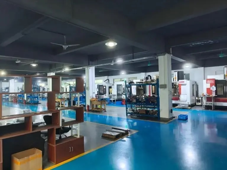
On a mill-turn center, the same part can be roughed from the outside and finished internally without a second setup. That removes the concentricity error you get when a part moves from lathe to mill. We run 16 mill-turn centers for exactly this reason: bore-to-OD relationships stay tight because the part never leaves the spindle.
If the bore is not round after a clean finishing pass, the problem is usually the setup, not the program. Check chuck pressure on thin-wall parts, check for a worn jaw, and check whether the bar is actually clamped on the full shank diameter.
- 1Rough firstOne solid pass beats many light ones on a long bar.
- 2Finish in one passAvoid re-entering the cut; it leaves a step.
- 3One setupMill-turn keeps bore and OD concentric.
- 4Check the setupOut-of-round often comes from clamping, not the tool.
Chatter, taper, and finish problems, and what to change first
Chatter has a frequency you can hear and a cause you can usually fix. Shorten the overhang, increase the bar diameter, or move to a damped bar. Changing speed helps, but only if you move far enough to leave the unstable zone. Small speed tweaks around a chattering condition rarely solve anything.
Taper shows up as a bore that measures small at the back. The bar pushes away from the cut at the unsupported end. A spring pass at the same setting often brings it back, but the better fix is a stiffer bar or a two-pass strategy where the finish pass removes a consistent 0.2–0.3 mm.
Poor finish on an otherwise stable bore usually traces to feed, nose radius or edge wear. A worn edge rubs instead of cutting, and the finish degrades before the size drifts. On long runs, change inserts on a count, not on a hunch.
Heat is the quiet one. A bore that measures on size when hot can shrink out of tolerance when it cools. On tight-tolerance work, let the part stabilize before final measurement. Our inspection runs a raw material check, in-process monitoring and a final check before shipment, with reports available on request.
- 1ChatterShorten overhang or go to a damped bar.
- 2TaperStiffer bar or a consistent finish allowance.
- 3Bad finishCheck edge wear and nose radius before speeds.
- 4Size driftLet the part cool before final measurement.
When internal turning is the wrong call
Not every hole should be turned. Cross holes, interrupted bores, and bores with a flat or a keyway break the cutting edge and shock a long bar. On those parts, helical milling on a 5-axis machine gives you a continuous cut with a shorter, stiffer tool and no bar deflection.
Very shallow large-diameter bores are another case. If the depth is under about 0.5× diameter, milling the bore with a circle interpolated path is often faster than setting up a boring bar and dialing it in. The tolerance is easier to hold, too, because the tool is short.
Deep small holes belong to gun drilling followed by a finish bore or ream. Trying to bore a Ø8 mm hole 150 mm deep on a lathe is a fight you will lose slowly. Choose the process that matches the geometry, and the tolerance follows.
We machine aluminium, stainless, steel, copper alloys, titanium and engineering plastics, so the process choice is made per part, not per material. A 6061 housing with a Ø40 mm bore at 3:1 is a straightforward boring job. The same bore in a thin-wall 17-4PH part may need a different approach entirely.
- 1Interrupted boresCross holes and keyways favour helical milling.
- 2Shallow large boresCircle milling is often faster than boring.
- 3Deep small holesGun drill, then finish with a ream or light bore.
Common questions about internal turning
What depth-to-diameter ratio can you hold on a bored hole?
Up to about 8:1 with the right bar and through-coolant, and better with a damped bar on small diameters.
Past that, gun drilling followed by a finishing pass is more reliable than trying to bore the full depth in one operation.
How do you stop chatter in a deep bore?
Shorten the overhang first, then increase bar diameter if the bore allows it. Move to a carbide or damped bar if those two steps are not enough.
Speed changes help only when you move well outside the unstable range. Small adjustments usually just shift the noise.
Can you hold ±0.005 mm in a turned bore?
Yes, on a stable setup with a rigid bar, controlled temperature and a finishing pass that removes a consistent allowance.
On thin-wall parts, springback after the cut is the limiting factor, so we plan the allowance and the clamping pressure around the wall thickness.
When should a bore be milled instead of turned?
When the bore is interrupted by cross holes or slots, when it is shallow and large, or when the part cannot be held in a lathe without distortion.
Helical milling with a shorter tool avoids the bar deflection problem entirely on those parts.
What surface finish is realistic inside a bore?
Ra 0.8–1.6 μm is a normal finishing target. Ra 0.2–0.8 μm is achievable with a wiper insert and a stable setup.
Blind bores and deep bores are harder, because chip recutting and coolant reach both degrade the finish.
Do you machine one-off bores as well as production runs?
Yes. There is no minimum order quantity, so a single prototype and a 10,000-part run go through the same process planning.
Quotation and a free DFM analysis come back within 12 hours, and production can start within 24 hours.
Send us the bore that keeps fighting you
Upload the drawing and we will tell you which process holds the tolerance, with a quote and DFM notes back within 12 hours.
12-hour quote100% inspectionNDA on request









