
Axis CNC Machining Solutions: Choosing the Right Setup
This page explains how 3, 4 and 5-axis machining differ, which part geometry actually needs the extra rotary axes, and how to read a quote that includes axis count, tolerance and finish. It is written for design engineers and sourcing engineers who have a drawing and need to pick a process, not a slogan.
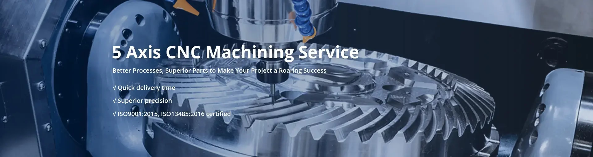
What axis count actually changes
Axis count is not a quality rating. It is a way to reach features that a three-axis machine cannot reach without moving the part.
Three-axis, four-axis and five-axis in practical terms
A three-axis mill moves the tool in X, Y and Z only. The tool always comes down from the spindle direction, so any feature on a side wall or a slanted face needs a second operation with the part re-fixtured. That second setup is where most tolerance stack-up comes from. If the drawing has one datum face and most features are reachable from it, three-axis is still the cheapest correct answer.
A four-axis machine adds rotation, usually around the X axis on a rotary table. This suits parts that are round or prismatic with features at intervals around a bore: flanges, manifolds, shafts with cross-drilled holes, cams. The part turns, the tool stays perpendicular to the axis. You machine four sides without re-clamping, but you cannot tilt the tool relative to the work.
Five-axis adds a second rotary axis. Either the table tilts and rotates (trunnion), or the spindle tilts and rotates. The cutting tool can now approach the workpiece from nearly any direction in one setup. That is the whole point. It removes setups, and it lets the tool tip away from the surface so the flank of the cutter does the work instead of the tip.
- 13-axisFlat plates, pockets, simple profiles. Lowest cost per part, most setups.
- 24-axisRound or indexable parts with features around one axis. One setup for four sides.
- 35-axisContoured surfaces, undercuts, angled holes, deep cavities. One setup, best accuracy.
Which parts belong on a five-axis machine
The clearest case is a part with features on five or six faces that must all be true to each other. Aerospace brackets, medical instrument housings, impellers and turbine-style blades, engine components with angled ports. If you re-fixture that part three times on a three-axis machine, each setup adds its own error and its own labour. Five-axis collapses it to one setup and one datum.
The second case is undercut geometry. A T-slot cutter or a lollipop cutter can reach some of it, but tool deflection and chatter usually ruin the finish. Tilting the tool 30–45° lets a shorter, stiffer cutter reach the same pocket wall. Short tools chatter less, so the surface comes out better and the cutter lasts longer.
The third case is surface finish on free-form shapes. A three-axis machine leaves visible step-over marks on a curved surface because the tool axis is fixed. A five-axis machine keeps the tool normal to the surface, so the scallops are small and vector-aligned. On a mold insert or an impeller, that can remove a manual polishing step.
When five-axis is the wrong choice
A flat plate with through-holes and a couple of pockets does not need five axes. The programming time and machine rate are higher, and the part will not be more accurate. Three-axis or a mill-turn cell will hold the same tolerance for less money.
Simple turned parts with a few milled flats are the natural home of a mill-turn center, not a five-axis mill. If the part is mostly rotational, turning is faster and the roundness is better.
Very large parts can also rule out five-axis. Our largest five-axis travels reach 4,000 × 400 × 150 mm, and the medium class covers 750 × 1,150 × 550 mm and 600 × 600 × 600 mm. Beyond those envelopes, or when the part weight exceeds what a trunnion can safely index, the job moves to a large three-axis machine with multiple setups.
Finally, five-axis does not fix a bad drawing. If the datum scheme is ambiguous or the tolerance is tighter than the function requires, more axes just add cost. A DFM review usually finds that first.
Axis count compared for typical part features
Use this as a first filter before requesting a quote.
| Part feature | Recommended axis count | Main reason |
|---|---|---|
| Flat plate, one datum face | 3-axis | Lowest setup cost |
| Flange with holes around a bore | 4-axis | Index without re-clamping |
| Angled port on a housing | 5-axis | One setup, true position held |
| Impeller or blade contour | 5-axis | Tool stays normal to surface |
| Undercut pocket, deep wall | 5-axis | Shorter, stiffer cutter |
| Shaft with cross holes | Mill-turn or 4-axis | Turning holds roundness |
| Mold insert, free-form | 5-axis | Less manual polishing |
How setups drive the tolerance you can hold
Every time the part leaves the fixture, error enters. Clamping stress releases, chips sit under a locating face, the operator re-zeroes to a different datum. Two setups on a well-controlled job might add 0.01–0.02 mm of position error between features. Five setups add more. Five-axis machining removes setups, which is why it is the practical route to ±0.005 mm on a complex part rather than a simple one.
The tolerance itself also depends on the feature. A bored hole in aluminium on a rigid setup holds ±0.005 mm routinely. A deep slot in 17-4PH stainless with a long reach tool is a different problem: tool deflection dominates and you may need to accept ±0.02 mm or plan a finishing pass with a shorter cutter.
Thermal drift matters on long cycles. A five-axis job that runs for hours will move as the spindle and the part warm up. We probe and re-set work offsets during the run on tight parts. That is an in-process step, not a claim about every part we ship.
Surface finish follows the same logic. We work to Ra 0.2–0.8 μm on fine finishes, Ra 0.8–1.6 μm on high-quality finishes, and Ra 1.6–3.2 μm as-machined. Getting below Ra 0.8 μm usually means a separate finishing strategy, sometimes with a smaller step-over or a different tool, and it costs cycle time.
- 1One setupBest feature-to-feature position, lowest labour.
- 2Each added setupNew datum error, new clamping stress, more labour.
- 3Long toolsDeflection raises the achievable tolerance.
- 4Fine finishSmaller step-over, more cycle time.
Materials and finishes that fit multi-axis work
Aluminium is the common case: 6061, 6061-T6, 2024, 5052, 5083, 6063, 6082, 7075 and ADC12 all machine well and hold tight tolerances on a five-axis setup. Stainless grades 303, 304, 316, 316L, 420, 430, 431, 440C and 17-4PH are harder on the cutter, so the toolpath and the finishing allowance need more thought. Steel grades 1018, 1045, 4130, 4140, 4340 and A36 appear in structural and automotive parts.
Titanium and high-temp alloys are where five-axis earns its place. TC4 (Ti-6Al-4V), TA1, TA2, Inconel and magnesium AZ31B / AZ91D all cut hotter and deflect more. Keeping the tool engaged and the toolpath smooth matters more than raw spindle speed. Copper and brass grades C101, C103, C110, beryllium copper, C27400, C28000 and C36000 are common in electrical and connector work.
Plastics are also routine: ABS, PC, PMMA, POM, PA, PEEK, PP, HDPE and carbon fibre. PEEK and carbon fibre are abrasive, so tool wear is the main cost driver, not machine time.
Finishes available after machining include anodizing in clear, colour, hardcoat and conductive types; electroless nickel, zinc, silver and gold plating; powder coating and black oxide; bead blasting, tumbling, brushing and polishing; and laser marking or engraving with a minimum character height of 1.5 mm.
Machine envelope and classes at GreatLight
Numbers below come from our current equipment list.
| Class | Travel or size | Typical use |
|---|---|---|
| Large 5-axis | 4,000 × 400 × 150 mm | Long structural parts |
| Medium 5-axis | 750 × 1,150 × 550 mm | Housings, brackets |
| Compact 5-axis | 500 × 500 × 450 mm | Small complex parts |
| Rotary table | Ø400 mm | Indexed round parts |
| Max processing size | 4,000 mm | Overall envelope limit |
Inspection and documentation
Inspection is 100% before shipment. That covers a raw material check, in-process monitoring during the run, and a final inspection against the drawing. Reports are available on request, and they are worth asking for on any part with a true-position callout or a tight surface requirement.
Our quality system is certified to ISO 9001:2015, IATF 16949:2016, ISO 13485:2016 and ISO 27001:2022. The last one covers information security, which matters if your drawings are confidential. Uploads are treated as confidential and an NDA is available on request.
On volume, there is no minimum order quantity. A single prototype and a 10,000+ part run go through the same process. Quotation and a free DFM analysis come back within 12 hours, and production can start within 24 hours once the design is released. Parts typically ship in 3–5 days. Our historical late-delivery probability is below 2%.
If you are unsure which axis count your part needs, send the STEP file and the drawing. We will tell you the setup plan, the achievable tolerance and where the cost sits.
Common questions about axis CNC machining solutions
Do I need to send a 3D model, or is a 2D drawing enough?
A STEP or IGES model plus a 2D drawing with tolerances and datums is the fastest route. The model defines the geometry; the drawing defines what you will accept.
If you only have a 2D drawing, we can quote from it, but we will flag any feature that cannot be verified.
How much does five-axis machining add to the part cost?
The machine rate is higher than three-axis, but the setup count is lower. On a part that would need three or four setups on a three-axis machine, five-axis often costs the same or less.
On a simple flat part, it costs more and adds nothing. We will tell you which case yours is.
What is the tightest tolerance you hold on a complex five-axis part?
We work to ±0.005 mm (±0.0002 in) on features where the setup and the material support it.
Deep pockets, long tools and hard alloys can push the practical limit to ±0.02 mm or looser. The DFM review states which applies to your part.
Can you machine a part with an undercut that no straight tool can reach?
Usually yes. A tilted tool on a five-axis machine reaches undercut walls that a three-axis machine cannot touch.
Send the model and we will confirm whether the feature is reachable and what tool is needed.
How do you handle confidential drawings?
Uploads are treated as confidential, and we can sign an NDA before you send files.
Information security is covered by our ISO 27001:2022 certification.
Can you move a prototype into production without re-quoting the whole part?
Yes. There is no minimum order quantity, so the same process runs from one piece to 10,000+ parts.
We keep the setup plan and inspection records from the prototype stage and carry them into the production run.
Send the drawing, get a setup plan
Tell us the geometry, material and tolerance. We will come back with a quote, a DFM analysis and the axis count we would use.
12-hour quoteFree DFM analysis100% inspectionNo MOQ









