
Basic Knowledge of CNC Software Documentation
This page covers what actually goes into CNC software documentation: the setup sheet, tool list, CAM notes, offsets and revision records that sit behind a program. It is written for engineers and buyers who need to audit or transfer a process, not just receive a part. After reading it you can judge whether a shop's documentation is complete enough to repeat a job six months later.
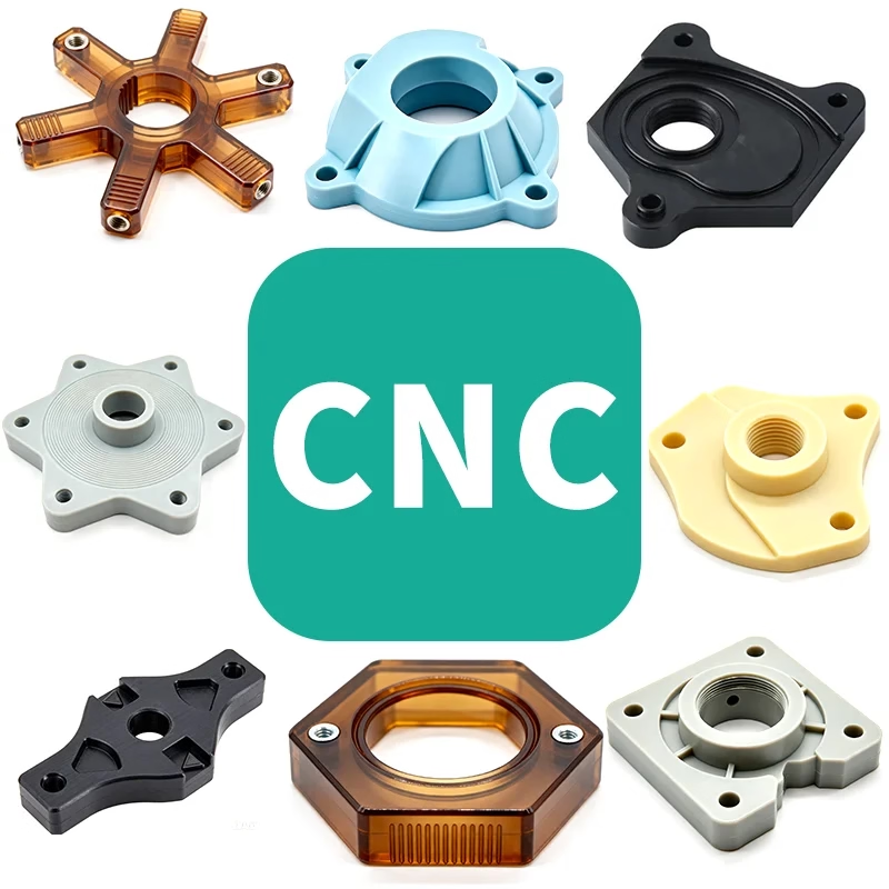
What CNC Software Documentation Covers
A program alone is not a process. The paperwork around it is what makes the part repeatable.
The Documents Behind a Cut Program
A CNC program is a text file of coordinates, feed rates and spindle speeds. On its own it tells a machine what to move, not why. Documentation is the layer that records the reasoning: which tool, which fixture, which offset, which revision of the model the code was posted from.
Most shops split this into a few recurring documents. The setup sheet lists workholding and zero position. The tool list names every cutter, its holder and its stick-out. The CAM notes capture stock size, residual material and rest-machining passes. The inspection plan states which features get measured and to what tolerance.
When a job runs once, thin documentation is survivable. The operator who set it up remembers the details. When the same part returns in a year, or moves to a second plant, or gets a design change on one feature, that memory is gone. Written records are the only thing that survives staff turnover and machine reassignment.
This matters most on tight work. A part held to ±0.005 mm depends on thermal state, clamping force and tool wear as much as on the code. If those variables are not written down, the next run starts from zero.
- 1Setup sheetWorkholding, datum, zero offset and fixture ID for each operation.
- 2Tool listCutter geometry, holder, stick-out, and which tools are pre-set offline.
- 3CAM notesStock definition, rest material, and the toolpath strategy behind each pass.
- 4Inspection planWhich features are measured, with what instrument, at what tolerance.
From CAD Model to Posted Code
The chain starts with a CAD model and a drawing that defines tolerances and datums. The CAM programmer imports the model, chooses a coordinate system, and decides how the part will be held. That decision drives everything downstream. Fixture choice sets the datum, the datum sets the zero offset, and the zero offset determines whether the posted coordinates land where the drawing expects.
Post-processing is where CAM output becomes machine-specific code. A post processor translates generic toolpaths into the dialect of a particular control. Two machines cutting the same part may need different posts. Documenting which post was used, and its revision, prevents a program from being rerun on the wrong machine with the wrong canned cycles.
Simulation and verification sit between CAM and the floor. Software checks for gouges, collisions and remaining stock before a cutter ever touches metal. The value of that check depends on how accurately the stock model, holder geometry and fixture are represented. A simulation run against a simplified model proves very little.
The output of this stage is a program plus a package: post version, simulation report, tool list and setup sheet. Shops that skip the package can still cut parts. They just cannot prove the process will repeat.
Documentation Elements and What They Prevent
Each element answers a specific failure mode seen on the floor.
| Element | Typical Content | Failure It Prevents |
|---|---|---|
| Setup sheet | Fixture ID, datum, zero offset, clamp sequence | Wrong zero, scrapped first article |
| Tool list | Cutter, holder, stick-out, preset length | Collision, wrong depth of cut |
| CAM notes | Stock size, rest material, stepover strategy | Uncut corners, tool load spikes |
| Post version | Control dialect, revision number | Canned cycle errors on a second machine |
| Simulation report | Gouge and collision check result | Crash on an unproven toolpath |
| Inspection plan | Feature, instrument, tolerance, sample rate | Unmeasured out-of-tolerance features |
| Revision log | Model rev, program rev, change reason | Cutting to an outdated drawing |
When Full Documentation Is Worth It
Not every job needs a twenty-page package. A one-off prototype in aluminium, cut on a three-axis mill to general tolerances, can run from a program and a sketch. The cost of writing full documentation exceeds the risk of a rerun. For that job, a tool list and a photo of the setup is enough.
The balance shifts with quantity, tolerance and geometry. Parts held to ±0.005 mm, five-axis work with compound angles, or runs above a few hundred pieces justify detailed records. So does anything destined for a regulated industry where traceability is a requirement rather than a preference.
There is a second trigger: transfer. If a part may move between plants, or between machines of different sizes, documentation is what makes that move cheap. Re-proving a process from scratch on a second machine can cost more than the original setup.
A practical rule: document to the level where a competent machinist who has never seen the part can set it up, run it, and inspect it without calling the programmer. If that person would need to ask a question, the gap is worth closing.
- 1Light documentation suitsOne-off prototypes, loose tolerances, single machine, single operator.
- 2Full documentation suitsTight tolerance, five-axis geometry, repeat runs, regulated industries.
- 3Transfer is a triggerAny part that may move between plants or machine sizes.
Revision Control and Version Naming
A program without a revision number is a liability. Two files named part_final.nc and part_final_v2.nc tell an operator nothing about which one matches the current drawing. A naming scheme that ties program revision to model revision removes that ambiguity. The convention matters less than applying it every time.
Change control works the same way on the floor as it does in engineering. When a feature changes, the model revision increments, the CAM file is re-posted, and the program revision follows. The setup sheet records which revision was proven. Older programs are archived, not overwritten. If a customer asks why a dimension moved between lots, the log answers the question.
Offsets and wear data deserve separate treatment. Tool length and diameter offsets are machine state, not program content. They change with every tool change. Documenting the nominal preset values, and the allowed wear band, keeps operators from compensating for a worn cutter by editing the program.
For shops running ISO 9001:2015 or IATF 16949:2016, revision control is audited, not optional. The same discipline that satisfies an auditor also shortens setup time on the next run.
Common Questions
What file formats should be included in a documentation package?
At minimum: a STEP or native CAD model, a 2D drawing with GD&T, the CAM file, the posted NC code, and a PDF setup sheet. Simulation reports and tool lists are usually PDF or spreadsheet.
Format matters less than consistency. A package where every job follows the same structure is easier to audit than one with mixed conventions.
Can a program be moved to a different machine without re-documentation?
Only if the post processor, control dialect, work envelope and tool holders match. A program posted for one control may use canned cycles or offset registers the second machine does not have.
In practice, moving a program means re-posting, re-simulating against the new machine's kinematics, and updating the setup sheet. The CAM notes and inspection plan usually carry over unchanged.
How much of this documentation is shared with the customer?
Usually the drawing, material certificates, inspection report and any PPAP-style package the industry requires. Setup sheets and CAM files are internal process documents.
Customers with a legitimate need for process data, such as a transfer of tooling, can request it under NDA. Uploads and shared files are handled as confidential.
Does documentation slow down a first-article run?
It adds a few hours of programming and review time. On a job that will be cut once and never again, that cost is hard to justify.
On anything with a repeat quantity, the time is recovered at the second setup. The operator reads the sheet instead of reverse-engineering the fixture.
What tolerance level makes an inspection plan necessary?
Once a feature is specified tighter than the general tolerance block, it should be named in the inspection plan with the instrument that measures it. Calipers are not suitable for every callout.
GreatLight inspects 100% of parts before shipment, with raw material checks, in-process monitoring and final inspection. Reports are available on request.
How is offset data kept from drifting between runs?
Record the nominal preset values for tool length and diameter offsets, plus an allowed wear band. Operators adjust within the band, not by editing the program.
When a tool is replaced, the preset is re-measured and the sheet is updated. That keeps the program as the single source of truth for geometry.
Send Us a Part With Tight Tolerances
Upload your model and drawing. We return a quotation and a free DFM analysis within 12 hours, with the process documentation your job actually needs.
12-hour quote100% inspectionNDA on request









