
Basic Knowledge of Sheet Metal Processing
This guide covers the basic knowledge sheet metal engineers need: how a flat blank becomes a formed part, which materials behave how, and where the process limits sit. It is written for design engineers and sourcing staff who review drawings and quotes. After reading it you can judge whether a part suits sheet metal or belongs on a mill.
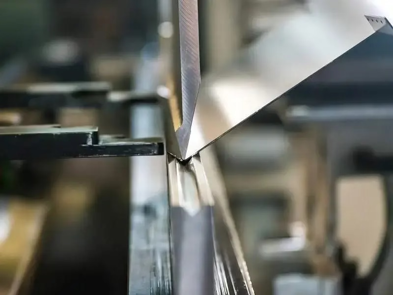
From flat blank to finished part
Formed parts move through a chain of steps. Each step leaves a mark the next one has to live with.
What actually happens between the drawing and the box
A formed part starts as a flat blank, not as a block of material. The blank is cut to a developed shape, then bent, then joined or finished. Every operation changes the geometry slightly, and the next operation inherits that change. This is why a drawing that looks simple can still be hard to hold.
The usual order runs: blanking, forming, joining, finishing, inspection. Blanking sets the outside profile. Forming creates flanges, bends and stiffening ribs. Joining adds hardware, rivets, welds or clinch nuts. Finishing coats or textures the surface. Inspection checks what the earlier steps did.
Tolerances stack along that chain. A ±0.1 mm blank tolerance plus a 1° bend angle error can push a hole out of position by more than ±0.3 mm on a long flange. Engineers who understand the stack can set realistic callouts. Engineers who do not often over-specify and pay for it.
Thickness matters more than most people expect. A 0.8 mm panel springs back differently than a 3 mm one, and the bend radius that works for one will crack the other. We look at thickness first when we review a formed part.
Choosing the right alloy for the job
Cold-rolled steel SPCC is the default for brackets and enclosures. It bends cleanly, takes powder coat well, and costs less than stainless. It rusts if left bare, so plan a finish from the start. Hot-rolled SHCC is thicker and rougher, used for heavy frames where surface appearance does not matter.
Galvanized sheet SECC and SGCC carry a zinc layer that resists corrosion without painting. The zinc is soft and can flake at a tight bend, so keep the inside radius at least equal to thickness. Welding galvanized steel releases zinc fumes; we prefer rivets or clinch joints on those parts.
Aluminium 5052 is the best forming grade in the common range. It bends without cracking and holds a radius well. Alloy 6061 bends less gracefully and is better left for machined details. Alloy 1060 and 1010 are soft and used for cosmetic panels. Copper and brass form easily but cost more and tarnish.
Stainless 304 and 316 resist corrosion and take a brushed or mirror finish. They work-harden, so a bend that starts fine can crack on a second hit. 301 and 430 are used where springback is wanted. Titanium and Inconel are possible but slow, and usually end up on a mill instead.
- 1Thickness under 1 mmWatch springback and handling dents.
- 2Thickness over 3 mmBend radius grows; consider machining.
- 3Coated stockProtect the coating at every step.
Common sheet materials and where they fit
A starting point, not a substitute for a drawing review.
| Material | Typical thickness | Forming behavior | Typical use |
|---|---|---|---|
| SPCC cold-rolled | 0.5–3.0 mm | Bends well, needs finish | Brackets, enclosures |
| SECC / SGCC | 0.5–2.5 mm | Zinc can flake at tight radius | Outdoor panels, chassis |
| 5052 aluminium | 0.8–4.0 mm | Best forming alloy | Covers, housings |
| 6061 aluminium | 1.0–5.0 mm | Limited bend, cracks | Machined details |
| 304 / 316 stainless | 0.5–3.0 mm | Work-hardens, cracks | Food, medical, marine |
| Copper C110 | 0.5–2.0 mm | Forms easily, tarnishes | Busbars, RF shields |
Where the real limits sit
Laser cutting holds ±0.1 mm on thin stock and leaves a clean edge. It costs more per part than punching but needs no tooling, so it suits prototypes and low runs. Punching wins above a few thousand parts because the tool amortizes. Waterjet cuts thick plate and heat-sensitive alloys without a heat-affected zone.
Bending is where most design problems surface. The inside radius should be at least equal to thickness for mild steel, and larger for aluminium and stainless. A hole placed too close to a bend will distort; keep it at least 2.5 times thickness away, plus the radius. Counterbores and slots near a bend need the same clearance.
Springback is the material pushing back after the punch lifts. Mild steel springs back about 1°, stainless and aluminium more. We compensate by over-bending or by coining, and we check the first part before running the rest. A bend angle callout of ±1° is realistic; ±0.25° usually is not.
Hardware insertion adds another step. Clinch nuts, standoffs and studs press into the sheet and need a flat area around them. Put them at least 1.5 times the nut diameter from an edge. Rivets work on thinner stock. Welded studs are stronger but distort thin panels.
What to call out, and what to leave alone
Sheet metal tolerances are looser than machining tolerances, and that is normal. A formed part might hold ±0.2 mm on a hole pattern and ±0.5 mm on an overall length. When a feature truly needs ±0.005 mm, it usually belongs on a machined insert rather than the sheet itself.
Finish choice follows function. Anodizing suits aluminium and comes in clear, color, hardcoat and conductive versions. Electroless nickel and zinc plating protect steel. Powder coat gives a thick, durable color layer but adds 0.05–0.1 mm per side, which can close a tight fit. Black oxide is thin and mainly cosmetic.
Bead blasting and brushing give a matte or directional look. Polishing brings stainless to a mirror. Laser marking handles part numbers and logos, with a minimum character height of 1.5 mm so the mark stays legible after coating.
We inspect 100% of parts before shipment. That covers raw material checks, in-process monitoring and a final dimensional pass. Reports are available on request, and qualification rate on our lines sits at 99.99%.
Habits that keep formed parts cheap and repeatable
Keep bends away from each other. Two bends closer than 3 mm make the tooling awkward and the second bend can pull the first out of shape. Space them by at least the material thickness plus the radius, and more if you can.
Standardize hole sizes and hardware across a product family. Fewer tools, fewer setup changes, lower cost. If a prototype uses M4 clinch nuts, keep M4 on the production version unless there is a real reason to change.
Avoid sharp inside corners on the blank. A small fillet at an internal corner spreads stress and stops a crack from starting. This matters most on stainless and aluminium, which crack more readily than mild steel.
Think about grain direction on rolled stock. Bending across the grain gives a cleaner result than bending with it. On parts that will be formed hard, note the grain direction on the drawing so the shop can nest accordingly.
Common questions
When should a part be machined instead of formed?
When the geometry needs tight tolerances, deep pockets, or features that cannot be produced by bending a flat blank. A part holding ±0.005 mm on multiple faces usually belongs on a CNC mill.
Forming wins on large, thin, mostly flat parts with a few bends. Machining wins on compact, thick, complex parts. Many assemblies use both: a formed housing with a machined insert.
How tight a bend angle can you hold?
±1° is realistic on mild steel for most parts. Stainless and aluminium spring back more, so the range widens.
If a design needs ±0.25°, expect tooling trials and a higher part cost. Sometimes a machined angle block is the better answer.
What is the minimum bend radius?
A common rule is one times material thickness for mild steel, and larger for aluminium and stainless. Alloy 5052 bends well at one times thickness; 6061 needs more.
Below the minimum, the outside of the bend cracks. We check the radius against the alloy and thickness during DFM review.
Do finishes affect fit?
Yes. Powder coat adds roughly 0.05–0.1 mm per side. Anodizing adds a few micrometres. Plating thickness varies by process.
If two coated parts slide or mate, call out the finished dimension, not the bare metal one. We can adjust the blank to compensate.
Can you handle low-volume runs?
Yes. There is no minimum order quantity. We run from a single prototype to 10,000+ part runs.
For low volume we use laser cutting and press brake forming, which need no hard tooling. At higher volume, punching and dedicated fixtures bring the unit cost down.
How do you protect drawings and files?
Uploads are secure and confidential. We can sign an NDA on request before you share files.
Our quality system is certified to ISO 9001:2015, IATF 16949:2016, ISO 13485:2016 and ISO 27001:2022, which covers information security.
Send a drawing, get a formed-part review
We reply with a quotation and free DFM analysis within 12 hours, and production can start within 24 hours.
12-hour quoteFree DFM analysis100% inspection









