
Bulk Rapid Prototyping Solution: Build 20 to 500 Parts That Match
This page is for design engineers and sourcing teams who need a few dozen to a few hundred functional prototypes from one supplier, not one vendor per process. It covers process selection, tolerance and finish planning, inspection scope, and the checks that tell you a supplier can hold the same result on part 1 and part 400.
What Changes When Prototype Volume Goes Up
A single prototype proves the design works. Fifty identical prototypes prove the process does.
Why 50 Parts Behave Differently Than One
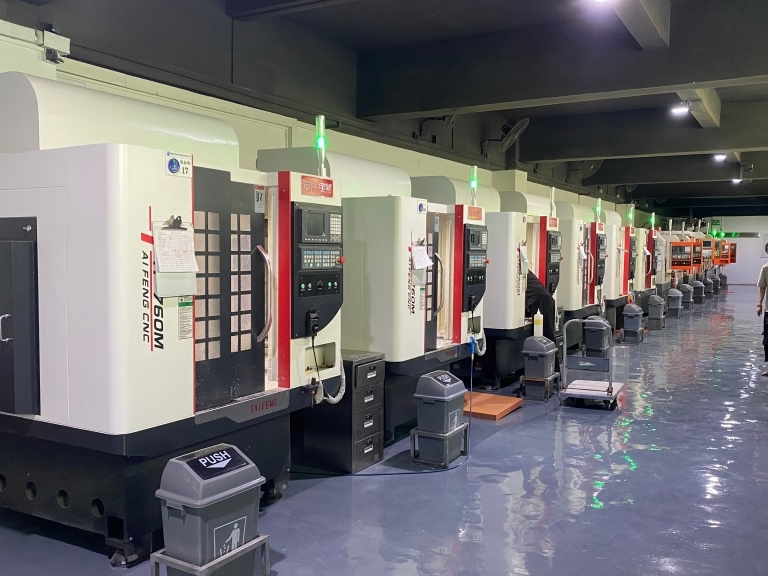
One prototype is a drawing check. You learn whether the geometry fits, whether the wall is thick enough, whether the assembly closes. Fifty parts is a process check. Now the question is whether the second part matches the first, and whether the fiftieth matches both. That gap is where most prototype programs lose time, because a shop that machines one-off parts by hand rarely has the fixtures, tool lists, and inspection records to repeat itself.
Volume also changes the economics. Setup, programming, and first-article inspection are fixed costs. Spread across 100 parts instead of two, they shrink to a small fraction of unit price. Material buying shifts too: a bar of 7075 aluminium cut into 100 blanks costs less per part than 100 separate cuts, and remnants from one order feed the next run.
The third change is traceability. Once prototypes go to a test lab, an EMC chamber, or a customer trial, someone will ask which revision a given part came from, which heat lot, and what its measured dimensions were. A bulk rapid prototyping solution that keeps every operation under one quality system answers that question from a file. Three vendors with three numbering schemes do not.
Choosing the Right Process for Each Part
No single process suits every part in a prototype batch. A metal bracket that carries load belongs on a CNC mill, where grain direction and wall thickness behave like production. A duct with internal channels that no tool can reach belongs on a printer. A transparent lens cover for a five-unit pilot build usually belongs in a vacuum casting silicone mold, because polishing ten CNC-machined acrylic domes costs more than casting them.
The useful rule is to sort parts by function rather than by looks. Structural parts, mating features, and anything that will be tested to failure go to machining. Non-structural covers, brackets that only locate, and ergonomic shells can go to printing or casting if the surface and tolerance allow. When a part must be both light and stiff, 3D printing with a topology-optimized shape followed by CNC finishing of the mating faces often beats either process alone.
Mixing processes inside one order also removes a coordination layer. Your engineer sends one set of drawings, one material callout, and one finish specification. The shop sequences the operations so that printed parts and machined parts arrive on the same pallet, with the same surface treatment where the design calls for it.
- 1CNC machiningMetal and engineering plastic parts that must hold ±0.005 mm and match production material.
- 23D printingComplex internal geometry, lightweight lattices, and shapes a cutter cannot reach.
- 3Vacuum castingTwo to fifty copies of a housing or cover in a production-like resin.
- 4Sheet metalEnclosures, brackets and chassis panels formed from 0.5–6 mm stock.
Where to Spend Tolerance and Where Not To
Prototype budgets go wrong when every dimension carries the same tight tolerance. A ±0.005 mm callout on a cosmetic edge costs inspection time and often forces a second operation, while adding nothing to function. The dimensions that decide whether the assembly works are usually a small set: bearing bores, mating faces, locating pin holes, and any feature that sets a gap or a preload.
A practical approach is to mark those functional dimensions on the drawing and leave everything else at general tolerance. That tells the programmer where to slow the feed, where to use a finishing pass, and where a roughing cut is enough. It also tells the inspector where to spend time with a micrometer instead of a caliper.
Surface finish follows the same logic. A sealing face may need Ra 0.8–1.6 μm, a sliding surface may need Ra 0.2–0.8 μm, and a mounting face inside a housing is fine at Ra 1.6–3.2 μm as machined. Asking for a mirror polish on a part that gets powder coated is money spent on nothing.
Process Selection by Part Function
Use this as a first pass, then confirm with the shop during DFM review.
| Part function | Recommended process | Typical material | Watch out for |
|---|---|---|---|
| Load-bearing bracket | 5-axis CNC | 6061-T6, 7075 | Thin walls under 1.5 mm deflect |
| Housing with internal ribs | 3D printing | ABS, PC, PA | Layer lines on sealing faces |
| Transparent cover, 10–50 pcs | Vacuum casting | PMMA-like resin | Shrinkage on long flat panels |
| Chassis panel | Sheet metal | 5052, 304 | Bend radius vs. hole location |
| Bearing bore, press fit | CNC turning | 1045, 17-4PH | Roundness, not just diameter |
| Ergonomic grip shell | 3D printing + CNC trim | PA, POM | Print orientation affects flex |
Holding the Same Result From Part 1 to Part 400
Repeatability comes from three things: fixtures, tool life records, and in-process checks. A soft jaw cut for the first part and never re-cut will drift. A tool that has cut 300 aluminium parts no longer holds the same corner radius. A shop that measures only the first article learns nothing about part 87.
The countermeasures are not exotic. Dedicated soft jaws or a vacuum plate for every operation. A tool change interval written into the setup sheet, not left to operator judgment. Dimensional checks at fixed intervals through the run, with the results recorded against the part serial. GreatLight runs 100% inspection before shipment, combining raw material verification, in-process monitoring, and a final check, with reports available on request.
For runs above roughly 200 parts, statistical process control becomes useful rather than academic. Plotting a critical bore diameter across the run shows whether the process is centered and whether it is drifting. If it drifts, the shop adjusts the offset before the first out-of-tolerance part is made, not after.
One Supplier or Three? How to Decide
Splitting a prototype batch across specialized vendors looks efficient on paper. In practice, the coordination cost lands on your engineering team. Three purchase orders, three lead times, three inspection formats, and three answers when a fit problem appears. Nobody owns the assembly tolerance, so nobody can fix it.
A single supplier makes sense when the batch contains parts that must fit together, when a common finish or material is required, or when the schedule is tight enough that a handoff would consume the buffer. Mixed technology under one roof also means one DFM review, so a machining limitation on one part can be designed out of a printed part before either is cut.
There are cases where splitting works. A very large casting or a specialized coating may genuinely sit outside a shop's equipment list. The test is whether the interface between vendors is simple. A part that bolts onto another part is a clean split. A part that shares a datum with another part is not.
What to Send and What to Expect Back
A bulk prototyping order moves faster when the input package is complete. Send 3D models in STEP or Parasolid, 2D drawings for anything with tolerances or threads, a material callout with the temper or grade, a finish specification, and the quantity per part number. Note which dimensions are functional and which are reference. If a part has a cosmetic surface, mark the direction of the grain or the print orientation on the model.
What comes back should be more than a price. A useful DFM response flags features that will need a second operation, walls too thin for the chosen process, tolerances that cannot be measured with standard equipment, and any part where a different process would cut cost without hurting function. GreatLight returns quotation and free DFM analysis within 12 hours, and production can start within 24 hours of approval.
Uploads stay confidential, and an NDA is available on request. For programs where the prototype is the product, that paperwork should be in place before the first model file leaves your network.
Common Questions
How many parts count as bulk prototyping?
There is no fixed line. The practical threshold is the point where hand-built methods stop being repeatable, which for most machined parts falls somewhere between 5 and 20 units.
Above that, fixtures, tool lists, and inspection intervals start to matter more than the machining time itself. Runs from one prototype to 10,000+ parts are handled the same way, with the process plan scaled to the quantity.
Can I mix materials in one prototype batch?
Yes. A single order can contain aluminium brackets, stainless shafts, printed housings, and cast covers. Each part gets its own process plan and inspection record, but they ship together on one pallet.
The benefit is assembly-level control. If a bracket and a housing share a datum, having both made under one quality system removes the arguments that appear when two vendors each claim their part is in tolerance.
What tolerance can you hold across a 100-part run?
±0.005 mm is achievable on critical features with the right fixturing and a controlled temperature environment. General dimensions can stay looser.
The important number is not the best single part but the spread across the run. A critical bore that holds ±0.005 mm on part 1 and drifts to ±0.012 mm by part 90 is a process problem, and it is caught by in-process measurement rather than by a final inspection alone.
How do you handle revisions mid-run?
Revision changes are normal in prototyping. The cleanest approach is to finish the current operation, stop the run, and restart from the changed model with a new revision number on the drawing and the parts.
Parts from the old revision are kept separate and marked. Mixing revisions in one bin is the fastest way to lose a week of test results, because nobody can tell afterward which geometry was measured.
Do you provide inspection reports?
Reports are available on request. Standard practice is raw material verification, in-process monitoring during the run, and 100% inspection before shipment.
For critical dimensions, a dimensional report lists the nominal, the tolerance, and the measured value per part or per sample, depending on the quantity and the criticality of the feature.
What is the lead time for a mixed 100-part batch?
Quotation and free DFM analysis come back within 12 hours, and production can start within 24 hours of approval. Machined parts typically ship in 3–5 days.
A batch that mixes machining, printing, casting, and finishing is paced by the longest operation, usually the finishing step. Sequencing is planned around that, so printed and machined parts are not waiting on each other.
Send Your Prototype Batch for Review
Upload your models and get a quotation with free DFM analysis within 12 hours. No minimum order quantity, from one prototype to a 10,000+ part run.
12-hour quoteNo MOQ100% inspectionNDA on request









