
Carbon CNC Machine Tips Guide
Carbon fiber reinforced polymer cuts cleanly on a CNC machine, but it does not behave like aluminium or steel. This guide is for engineers and buyers who need to plan tooling, dust control, workholding and inspection before a CFRP part goes to the spindle. You will be able to judge which features are practical and where the process gets expensive.
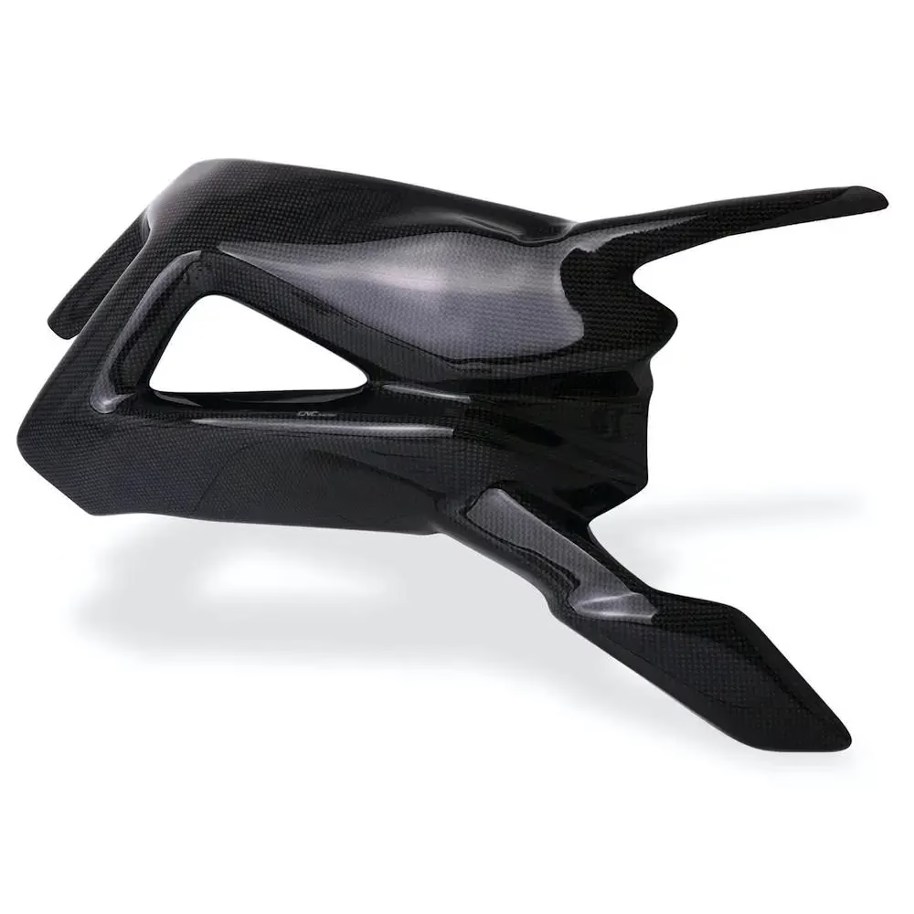
What changes when the workpiece is carbon fiber
The machine stays the same. The tool, the fixture and the cleanup change.
Why carbon fiber machines differently from metal
Carbon fiber reinforced polymer is a laminate. The carbon fibers carry the load and the epoxy holds them in place. When a cutter meets the part, it does not shear a continuous chip the way it does in 6061 or 304. It fractures fibers, cuts resin and throws a mix of powder and short splinters. That difference drives almost every other decision on this page.
Abrasion is the first problem. Cured carbon fiber is harder than most tool steels at the cutting edge, so a high-speed steel end mill dulls fast. Uncoated carbide wears quickly too. The second problem is heat. Epoxy softens and can burn long before the fiber breaks, and a hot edge smears resin across the cut instead of shearing it. The third problem is the dust, which is conductive and does not break down in the body.
Because of this, a carbon CNC machine setup is judged on three things at once: edge quality, tool life and dust containment. Improve one and you can easily hurt another. A slow feed reduces dust but rubs the resin. A fast feed keeps the edge cool but pulls fibers and leaves fuzz. The working window is narrower than for aluminium, so the parameters need to be set on the material data sheet, not copied from a metal job.
- 1Abrasive fiberCarbide or diamond tooling, not HSS
- 2Heat-sensitive resinKeep the edge cool with feed, not with dwell
- 3Conductive dustVacuum at the cut, sealed enclosure
- 4Layer structureWatch delamination at the exit side
Tool selection and cutting parameters for CFRP
For most CFRP parts, a diamond-coated carbide router or a solid diamond burr is the right starting point. Diamond coating survives the abrasion far longer than TiAlN or AlCrN, which are designed for steel and stainless. On thick laminates and on parts with many holes, polycrystalline diamond (PCD) tooling pays back through tool changes alone. Two-flute and three-flute geometry clears chips well; higher flute counts pack the flutes with powder and raise cutting temperature.
Spindle speed usually sits high, often 12,000–20,000 rpm on a router, because the small chipload keeps the fiber from being pulled. Feed per tooth is small, typically 0.02–0.10 mm, and the depth of cut is set to take a clean pass rather than a heavy one. Climb milling gives a better edge on the top ply. On a metal-cutting machine, we run conservative parameters and let the diamond tool do the work instead of pushing feed rates.
Coolant is a decision point. Flood coolant controls heat and dust but wets the laminate and needs disposal. Dry machining with strong extraction is common for flat panels and is easier to keep clean. A mist of air keeps the edge cool without soaking the part. For parts that will be bonded or painted later, dry cutting plus vacuum is usually the safer route because no residue is left in the cut.
- 1Diamond coatingLongest life on abrasive laminate
- 2PCD for volumeWorth it when hole counts are high
- 3Low feed per tooth0.02–0.10 mm to avoid fiber pull-out
- 4Climb millingCleaner top ply on panels
Starting parameters for common CFRP operations
Values are starting points for diamond-coated carbide tooling. Confirm on the first article.
| Operation | Speed | Feed per tooth | Notes |
|---|---|---|---|
| Panel profiling, 2–5 mm | 14,000–18,000 rpm | 0.05 mm | Climb cut, vacuum at the cut |
| Pocketing, 5–10 mm | 10,000–14,000 rpm | 0.04 mm | Step down 1–2 mm per pass |
| Hole drilling, Ø3–Ø8 mm | 6,000–10,000 rpm | 0.03 mm/rev | Backing plate stops exit delamination |
| Countersink / chamfer | 8,000–12,000 rpm | 0.02 mm | Sharpen or replace at first sign of smear |
| Trimming of cured laminate | 12,000–16,000 rpm | 0.06 mm | Rigid fixture, minimum overhang |
Workholding, dust control and part geometry
Carbon fiber panels are thin, stiff and springy. Clamping pressure that would be fine on an aluminium block can bow a 2 mm laminate and cut a taper into the part. Vacuum tables with a sacrificial layer work well for flat panels because the load is spread evenly. For curved or boxed parts, we build a close-fitting nest in aluminium or a machined epoxy tool and support the part under the cut, not just at the edges.
Dust control is not optional. The powder is conductive, so it can short electronics and it will not settle in a normal shop filter. We use a sealed enclosure with high-volume extraction at the cutter and a HEPA stage, plus wet wipe-down before the part is handled at the inspection bench. Operators wear a respirator and gloves. On a carbon CNC machine, the extraction ducting is part of the process, not an accessory.
Geometry is where the design meets the process. Through holes and open profiles are straightforward. Deep pockets with vertical walls and small corner radii are harder because the tool needs to clear the chip and the tool deflection rises. Thin ribs under 1 mm and sharp internal corners are the two features that most often push a CFRP part from routable into a redesign. Add a backing plate on the exit side and give the cutter a corner radius where the design allows.
- 1Vacuum tableEven load on thin panels
- 2Machined nestSupport under curved and boxed parts
- 3HEPA extractionConductive dust must not recirculate
- 4Exit backingPrevents delamination on through holes
Inspection and finishing after machining
The defects that matter on CFRP are delamination, fiber pull-out, fuzz on the trimmed edge and resin burn. A visual check under good light catches most of them, and a 10× loupe on the cut edge tells you whether the fiber is sheared cleanly. For hole positions on structural parts, a CMM check confirms that the laminate has not moved during the cut. We inspect 100% of parts before shipment and keep reports on request.
Tolerances on a carbon CNC machine depend on the fixture as much as the spindle. Our machines hold ±0.005 mm on metal, and on CFRP we hold the drawing tolerance where the part is properly supported. Where the laminate is unsupported, spring-back can add several tenths. If a feature needs a tight fit, tell us which surface it lands on so the fixture can be built around it.
Finishing is limited on carbon fiber. Sanding and edge sealing are common; anodizing and plating do not apply. If the part needs a painted or bonded surface, we leave the cut dry and clean rather than applying any wet process that could leave residue in the laminate. Laser marking works for part numbers, with a minimum character height of 1.5 mm. Bead blasting is possible on some laminates but it opens the surface, so we confirm on a sample first.
- 1Visual + loupeCheck the trimmed edge at 10×
- 2CMM on hole patternsConfirms no movement during cutting
- 3Edge sealingSeals exposed fiber on trimmed faces
- 4Dry cut for bondingNo residue left in the laminate
Questions engineers ask before a CFRP job
Can you machine carbon fiber on the same machine as aluminium?
Yes, with a setup change. The tooling, extraction and cleaning routine differ, and the machine needs a full wipe-down between materials so carbon dust does not contaminate the next metal job. We keep CFRP work in a machine with sealed extraction and HEPA filtration.
What tolerance can you hold on a carbon fiber part?
On well-supported features we hold the drawing tolerance, and our machines are capable of ±0.005 mm. Thin unsupported sections can spring back by several tenths, so the achievable number depends on the part geometry and the fixture. Send the drawing and we will tell you which features are tight and which need a design tweak.
How do you stop delamination on drilled holes?
A sharp diamond-coated drill, a moderate feed, and a backing plate or sacrificial layer under the exit side. Peck drilling on thick stacks helps clear powder. If the hole is critical, we drill undersize and ream to final diameter.
Is dry machining or coolant better for CFRP?
It depends on the part. Dry cutting with strong extraction is cleaner and leaves no residue for bonding or painting. Coolant controls heat and dust better on deep pockets and long runs but requires disposal and a post-cut clean. We choose per job and confirm on the first article.
What is the maximum part size you can machine?
Our largest travel is 4,000 × 400 × 150 mm, and we also run 750 × 1,150 × 550 mm and 600 × 600 × 600 mm machines. We have 127 high-precision CNC machines, including 16 simultaneous 5-axis centers, so panel work and complex 3D shapes can both be handled in-house.
Do you sign an NDA for carbon fiber work?
Yes. Uploads are secure and confidential, and we sign an NDA on request before drawings are shared. You can also start with a quote and a free DFM analysis within 12 hours to see whether the features are practical before committing to production.
Send a carbon fiber drawing and get a process review
Upload the file and we will return a quote with DFM notes on tooling, fixturing and dust control within 12 hours.
12-hour quoteFree DFM analysis100% inspectionNDA on request









