
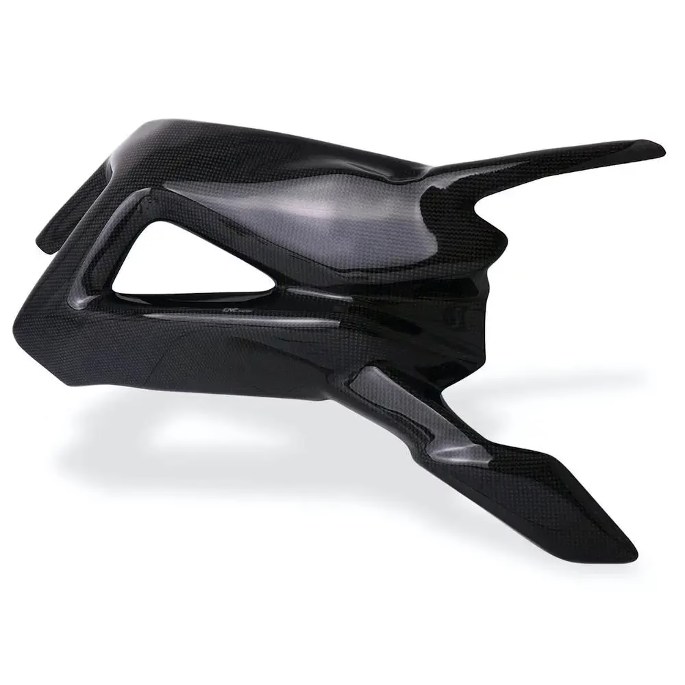
Carbon CNC machining with complex geometric shapes
Complex carbon parts are unforgiving: the fiber direction decides how the tool cuts, and the dust decides how the shop runs. This page covers which geometries we can mill in carbon fiber and graphite, how we fixture them, what tolerance actually holds, and when carbon is the wrong material. Written for design and manufacturing engineers who need a decision, not a brochure.
What makes carbon parts harder to machine than aluminum
The tools are not the problem. The material structure and the dust are.
Why the fiber direction changes your toolpath
Carbon fiber reinforced polymer is not a homogeneous block. It is layers of fiber held in resin, and the fiber runs in one direction inside each ply. A cutter that moves across the fiber gets a different result than one that moves along it. Edge quality, delamination risk and tool wear all shift with direction. This is the single biggest difference between carbon CNC machining and cutting aluminum or steel.
In practice we plan the toolpath around the ply orientation the customer specifies. Climb milling with a sharp, coated cutter keeps the fiber in compression and reduces fraying at the exit edge. Where the geometry allows, we enter and exit the cut at a shallow angle instead of dropping straight into a wall. On thin ribs this is the difference between a clean edge and a delaminated one.
The second factor is resin. Resin softens with heat, and heat builds up fast when a small cutter removes a lot of material in one pass. We control this with moderate spindle speeds, conservative feed per tooth and air blast instead of flood coolant. Water-based coolant on a carbon part can wick into exposed edges and damage the resin over time.
Graphite behaves differently again. It is brittle and abrasive, cuts like a powder, and produces a very fine conductive dust. Graphite electrodes for EDM are usually machined dry with strong extraction, and the toolpath is written to avoid sharp internal corners where the material chips out.
- 1Fiber direction sets the cutPlan the toolpath around ply orientation, not around the model only.
- 2Sharp tools, light passesDull tooling delaminates carbon faster than it wears out.
- 3Air blast over flood coolantKeeps the resin cool without letting moisture into exposed edges.
- 4Graphite cuts dryFine conductive dust has to be extracted at the source.
Which complex geometric shapes we can hold on a mill
A five-axis machine reaches features that a three-axis setup cannot, because the tool stays normal to the surface instead of approaching from one direction. That matters for carbon parts with curved pockets, angled ribs or undercut flanges. We run 16 simultaneous five-axis machining centers, with a 4,000 mm maximum processing size for long parts and a Ø400 mm rotary table for parts that need indexing around a bore.
Typical carbon geometries that go on the five-axis machines include monocoque panels with sculpted pockets, drone and UAV frame plates with tapered ribs, thin-walled housings with internal bosses, and brackets that blend three or four faces in one continuous surface. If a design can be reached from five directions without the tool shank hitting the part, it is usually machinable.
The geometry that gives us trouble is not the curved surface. It is the combination of thin walls and tight internal corners. A wall under about 1 mm deflects under cutting force, and a sharp internal corner concentrates stress and chips out. Where the drawing allows, we ask for a corner radius of at least one third of the wall thickness and a uniform wall section. Small design changes at that stage save a lot of scrap later.
Deep cavities with a high depth-to-diameter ratio are the other common limit. A long, thin cutter has to run at reduced feed and reduced depth of cut, and on abrasive carbon that means fast tool wear. Sometimes the right answer is to split the part into two pieces that are bonded or fastened, rather than to machine one deep pocket.
- 1Five-axis reachCurved pockets and multi-face blends machine in one setup.
- 2Thin walls need supportBelow roughly 1 mm, deflection shows up in the final inspection.
- 3Radius the internal cornersOne third of wall thickness is a workable rule of thumb.
- 4Deep pockets slow downLong small cutters wear quickly in abrasive carbon.
Carbon geometry and the machine that handles it
Machine assignments below are from our own shop floor. Tolerance refers to the finished machined feature, not the as-molded blank.
| Geometry type | Machine | Typical tolerance | Notes |
|---|---|---|---|
| Sculpted panel pockets | 5-axis, 4,000 mm travel | ±0.005 mm | Long parts stay on one setup |
| Tapered ribs and frame plates | 5-axis, 750 × 1,150 × 550 mm | ±0.005 mm | Thin ribs need light finishing passes |
| Bores indexed around an axis | 4-axis with Ø400 mm rotary | ±0.005 mm | One setup for concentric features |
| Flat plates and simple profiles | 3-axis, 500 × 500 × 450 mm | ±0.005 mm | Lowest cost route for flat work |
| Graphite EDM electrodes | 3-axis, dry cutting | ±0.005 mm | Extraction required at the cutter |
| Turned composite bushings | Mill-turn center | ±0.005 mm | Combine turning and milling in one run |
Holding a part without crushing it
Carbon laminates are stiff along the fiber and weak through the thickness. A vise tightened the way you would tighten it on a steel block will crush the laminate or leave a witness mark that cannot be polished out. We fixture carbon on custom soft jaws, vacuum chucks or sacrificial backing plates, and we spread the clamping load over a wide area rather than a point.
Vacuum workholding suits flat panels and thin plates. The whole back face is supported, so the part cannot bow while the cutter pushes down on it. For a panel with pockets on both sides, we machine the first side on vacuum, flip it onto a machined backing plate that matches the pocket pattern, and cut the second side with the first side fully supported.
For contoured parts we often machine a sacrificial fixture from aluminum or tooling board that matches the part's outer surface. The carbon blank sits in that nest for the finishing passes. It costs one extra setup, but it holds wall thickness far more consistently than clamps, and it protects the finished surface from the jaw.
One more point on sequencing. Rough and finish in separate operations. Roughing removes the bulk with a stronger cutter and leaves a small allowance, then a finishing pass takes that allowance with a sharp tool at high spindle speed. Trying to do both in one pass is where most delamination and chatter marks come from.
- 1Spread the loadSoft jaws, vacuum or a matched nest instead of point clamps.
- 2Support the back faceUnsupported thin panels chatter and bow during cutting.
- 3Rough then finishTwo operations keep edge quality and wall thickness stable.
- 4Protect the surfaceA nested fixture keeps finished faces away from metal jaws.
Checking a complex carbon part and finishing the edges
Inspection on a complex composite part is mostly about features that are hard to reach with a caliper. We use CMM probing for hole position, wall thickness and profile on curved surfaces, and we can supply inspection reports on request. Every part gets a raw material check, in-process monitoring and a final inspection before it leaves the shop.
Tolerance is a conversation, not a default. We hold ±0.005 mm on machined metal features, and that number is realistic on machined carbon features too when the part is rigidly supported and the feature is measured at a stable temperature. On a thin, unsupported composite skin, the part itself moves more than the machine does, and the honest answer is that the tolerance should be opened or the geometry changed.
Edge finish matters more on carbon than on metal. A sawn or roughly milled edge exposes fiber and is the usual starting point for delamination. We deburr and sand machined edges, and where the drawing calls for it we apply a sealing coat. Bead blasting gives a uniform matte surface on flat areas but will round a sharp edge, so it is specified only where the edge is not functional.
Carbon fiber appears in our plastics list alongside ABS, POM, PEEK and PA. If your part is a composite with a metal insert, we machine the metal features and the composite in the same program where the geometry allows, which keeps the insert position tied to the composite surface instead of to a second setup.
- 1CMM on curved featuresProfile, wall thickness and hole position, report on request.
- 2Tolerance follows rigidity±0.005 mm holds when the part is supported and stable.
- 3Edge sealing stops delaminationExposed fiber at a cut edge is where failure starts.
- 4Metal inserts in one programKeeps insert position tied to the machined composite face.
When carbon is the wrong choice
Carbon earns its cost when stiffness per kilogram drives the design. If the part is a stiff bracket that sees modest load, aluminum 6061 or 7075 will be cheaper, faster and easier to rework. Carbon also loses on parts with many small threaded holes, because threads in a laminate pull out under load and need metal inserts, which adds operations.
Cost is geometry-driven, not material-driven, on most carbon jobs. A simple flat plate in carbon is not much harder to make than the same plate in aluminum. A deep pocket with a 0.8 mm wall is a different project, and the price reflects the fixturing, the slower feeds and the scrap risk. That is why we quote from the model rather than from a material list.
If your part is still in the prototype stage and the geometry is not frozen, it is worth running the first version in aluminum or a cheaper composite to prove the shape, then switching to carbon once the design settles. We support both routes with no minimum order quantity, from one prototype to 10,000+ part runs.
Where carbon does win clearly: UAV and drone structures, robotic arms where mass at the end of the arm matters, motorsport and automotive body panels, medical imaging components that must be radiolucent, and any bracket where vibration and weight combine. Our aerospace and robotics teams handle most of that work.
- 1Choose carbon for stiffness per kilogramNot for parts that are simply flat and lightly loaded.
- 2Threads need insertsDirect threads in laminate pull out under load.
- 3Prototype in aluminum firstProve the geometry before paying for composite stock.
- 4Good fitsUAV frames, robot arms, radiolucent medical parts.
Questions engineers ask before sending a carbon part
Can you machine carbon fiber and metal inserts in the same setup?
Yes, when the insert sits on a face the cutter can reach without the tool shank hitting the composite. We machine the metal features and the composite surface in one program so the insert position stays tied to the machined face.
If the insert is buried inside a closed pocket, it usually needs a second operation. Send the assembly drawing and we will say which route applies.
What wall thickness can you hold on a carbon part?
Down to about 1 mm on a supported wall, with a uniform section and radiused internal corners. Below that, cutting force deflects the wall and the finished thickness varies more than the drawing allows.
The practical answer depends on the depth of the wall and how it is supported. A short 0.8 mm rib on a rigid panel is workable. A tall 0.8 mm wall standing free is not.
Do you cut dry or with coolant?
Carbon fiber is cut with air blast or dry with extraction. Water-based coolant can wick into exposed edges and affect the resin. Graphite is always cut dry because the dust is conductive and has to be extracted at the cutter.
Metal parts that are machined alongside carbon use normal coolant, in a separate operation.
How do you handle carbon dust in the shop?
Carbon and graphite machines run with local extraction at the tool and enclosed work areas. Operators use appropriate personal protection. The dust is managed as a waste stream rather than swept into the general shop.
If your part is a graphite electrode or a large dry-machined composite, this is part of why the setup takes longer than an aluminum job.
What files do you need for a quote on a complex carbon part?
A STEP or IGES model is best, plus a 2D drawing for tolerances, critical features and any surface finish callouts. Tell us the ply orientation if it is fixed.
We return a quotation and a free DFM analysis within 12 hours. Uploads are handled as confidential and an NDA is available on request.
Can a complex carbon geometry be split into two bonded parts instead of one machined part?
Often yes, and it is cheaper. A deep pocket with a high depth-to-diameter ratio is slow to machine and wears tooling fast. Splitting the part lets each half be machined with a shorter, stiffer cutter.
The trade-off is the joint. If the bond line or fasteners carry load, that has to be designed in from the start, not added at the end.
Send the model and we will tell you what the geometry needs
Upload a STEP file for a quotation and a free DFM analysis within 12 hours. No minimum order quantity, from one prototype to 10,000+ part runs.
12-hour quoteFree DFM analysisNDA on request









