
01
Hole walk on curved or angled surfaces
A standard twist drill enters a convex or sloped face and the tip slides before it bites. The hole lands 0.2–0.5 mm off position, the bolt no longer lines up, and the assembly gets reworked or scrapped.
Holes, threads and counterbores on small and mid-size batches. We review your DXF or STEP file, check depth-to-diameter ratio and exit conditions, then quote in 12 hours with a DFM note.
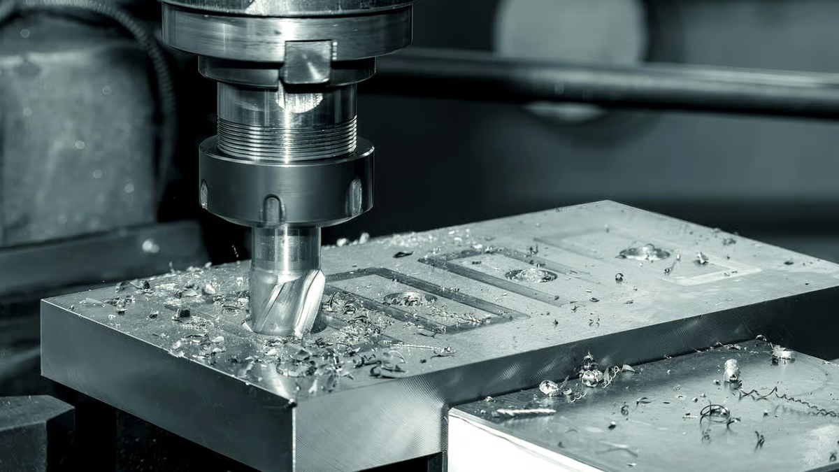
Four failures that show up on the shop floor, not in the model.
A standard twist drill enters a convex or sloped face and the tip slides before it bites. The hole lands 0.2–0.5 mm off position, the bolt no longer lines up, and the assembly gets reworked or scrapped.
Breakout burrs on a hydraulic manifold or a sliding fit block cost you deburring time and can block a passage. On thin walls the drill can also push material out instead of cutting it, so the exit face has to be milled back.
Past a 5:1 depth-to-diameter ratio, chip evacuation becomes the limiting factor. Coolant cannot reach the tip, heat builds up, and the hole ends up tapered or out of round by the time it breaks through.
One good first article does not prove a batch. Fixture wear, thermal growth and tool changes move hole centers over a 500-piece run, so parts 400–500 fail a go/no-go gauge check at final inspection.
Three decisions that decide whether the holes repeat.

Most hole position errors come from the setup, not the spindle. We clamp on a machined face or a dedicated soft jaw so the part cannot shift under thrust, and we spot-drill every location before the full-diameter tool touches the workpiece. On curved or angled surfaces we use a spot drill with a point angle matched to the following drill.
For a part with 30 or 40 holes, we often drill on a 3-axis or 4-axis machine with a rotary table and one work offset. Five-axis positioning is reserved for holes on compound angles that would otherwise need a second setup.
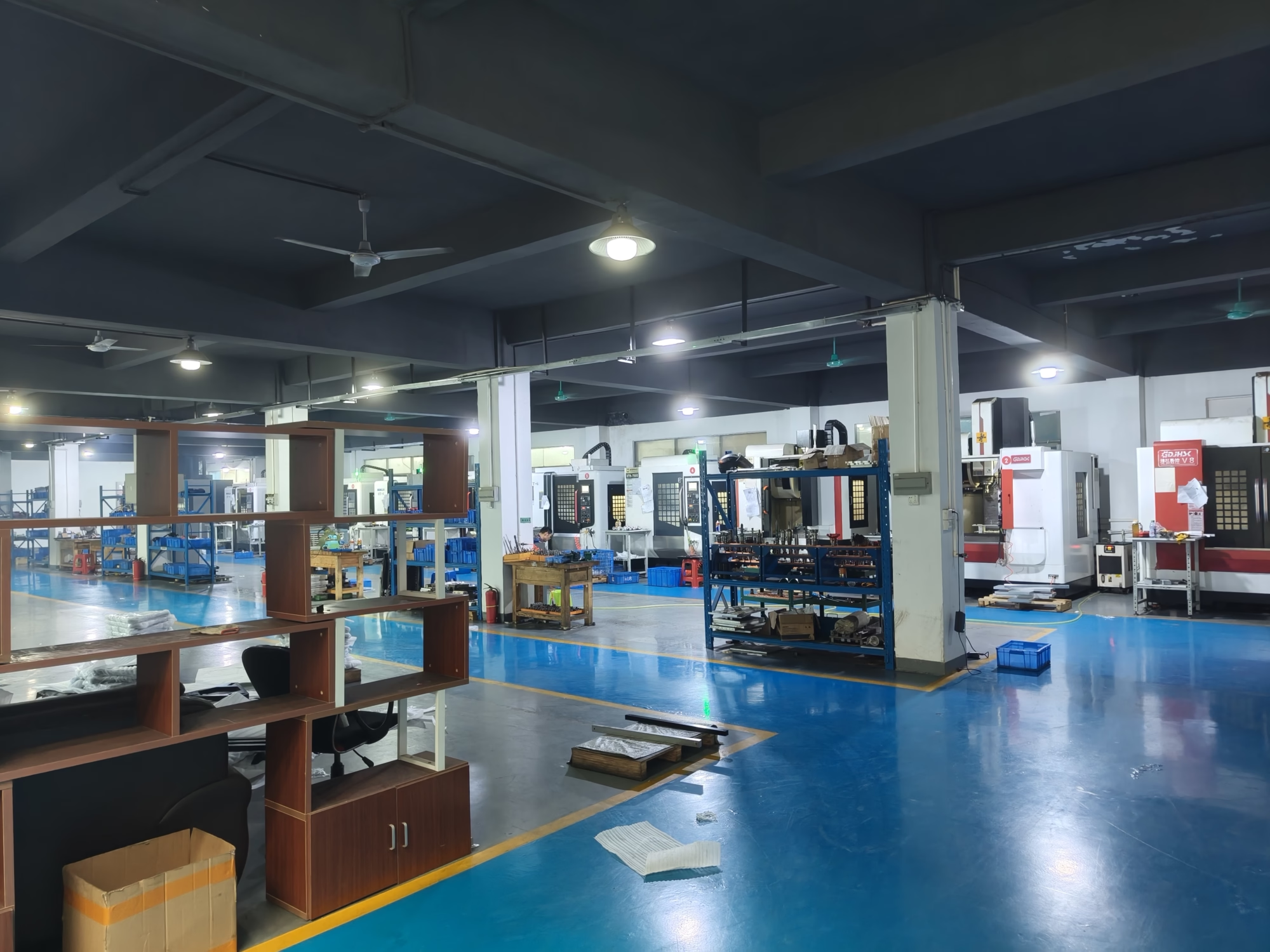
Drilling parameters change with material, not with the machine. A 6 mm hole in 6061-T6 runs at high surface speed with a light peck. The same hole in 316L stainless runs slower with more coolant and a shorter peck cycle, because work hardening at the tip will dull the margin in a few holes.
For holes deeper than 5× diameter, we switch to a through-coolant drill or a gundrill on a vertical deep-hole machine. For interrupted cuts in castings, we reduce feed at the entry and exit to keep the insert from chipping.
Match the feature to the process before you ask for a quote.
| Feature | Recommended method | Typical limit |
|---|---|---|
| Hole up to 5× diameter | Standard twist drill, spot first | Ø0.5–80 mm |
| Hole 5×–20× diameter | Through-coolant drill, peck cycle | Straightness within 0.05 mm |
| Hole over 20× diameter | Gundrilling on deep-hole machine | L/D up to 30:1 |
| Hole on a compound angle | 5-axis positioning, one setup | Angles 0–90° |
| Threaded hole | Drill, then tap or thread mill | M1.6 and up |
| Counterbore or spot-face | Drill, then flat-bottom or piloted tool | Flatness 0.02 mm |
Most parts need more than a hole. These are the operations we run in the same shop.
Ø0.5–80 mm holes, spot drilling, peck cycles, counterbores and spot-faces on 3-axis, 4-axis and 5-axis machines.
Cut and form taps from M1.6 up, plus thread milling for large diameters and thin-wall parts where a tap would distort the hole.
Faces, pockets and slots around the drilled features, and turned diameters on the same part from mill-turn centers.
Vertical deep-hole machines for long, straight bores in manifolds, mold plates and hydraulic blocks.
Manual and tumbled deburring, chamfering of hole entries, and controlled edge break on breakout faces.
Anodizing, plating, black oxide, bead blasting and laser marking, with masking around critical holes where needed.
| Item | Range or detail |
|---|---|
| Hole diameter | Ø0.5–80 mm |
| Position tolerance | ±0.005 mm on critical hole patterns |
| Maximum part size | 4,000 mm |
| Depth-to-diameter ratio | Up to 30:1 with gundrilling |
| Materials | Aluminum, stainless, steel, brass, copper, titanium, plastics |
| Finishes | Anodizing, plating, black oxide, bead blasting, laser marking |
| Batch size | From one prototype to 10,000+ part runs |
| Inspection | 100% before shipment, reports on request |
Held on critical patterns and checked with a CMM or pin gauges at final inspection.
16 simultaneous 5-axis centers, 12 four-axis mills, 27 three-axis machines and 16 mill-turn centers.
Drawing review, hole-by-hole DFM notes and pricing returned within 12 hours.
Material and tooling confirmed, machining can begin the next working day.
Raw material check, in-process monitoring and final inspection before any part ships.
Long rails and plates drilled on machines with a 4,000 × 400 × 150 mm travel.

Thin ribs around close-tolerance holes, with breakout burrs controlled on both faces.

Repeatable hole patterns across production runs, with IATF 16949 process control.
Small-diameter holes and cross-ports with clean internal passages and documented inspection.

Deep intersecting bores drilled straight enough to keep flow paths aligned.
We drill from Ø0.5 mm to Ø80 mm. For depths beyond 20× diameter we move to a gundrill on a vertical deep-hole machine, which keeps the bore straight enough for hydraulic and manifold work.
Anything past about 5× diameter should use through-coolant, so tell us the depth in the drawing rather than a note in the email.
We spot-drill with a point angle matched to the following tool, or mill a small flat where a spot drill cannot bite. On compound angles the part is positioned on a 5-axis machine so the entry is normal to the surface.
If the geometry still leaves a weak entry, we will say so in the DFM note and suggest a change, such as moving the hole off the slope or adding a boss.
Yes. Drilling, counterboring and tapping normally run in one setup on the same machine. That removes a re-clamp and keeps the tap concentric with the drilled hole.
For thin-wall parts we often thread-mill instead of tapping, because the cutting force is lower and the wall does not distort.
±0.005 mm is achievable on critical hole patterns, and we inspect those with a CMM or pin gauges. General holes are often fine at ±0.05 mm, and holding everything to the tighter number only adds cost.
Send the functional requirement, not a blanket tolerance, and we will tell you which holes actually need the tight callout.
No minimum order quantity. A single prototype and a 10,000-piece run both go through the same process, though unit cost drops as batch size grows.
For a one-off, the setup and programming time dominate the price. That is normal for drilling work.
We chamfer hole entries and control the breakout side, then deburr manually or by tumbling depending on the part. Internal passages get checked so no chip or burr blocks a flow path.
If the drawing calls for a specific edge break, such as 0.2 mm × 45°, tell us and we will hold it.
A STEP or DXF file plus material, quantity and any critical tolerances. A PDF with the hole callouts helps us flag issues faster.
We return pricing and a DFM note within 12 hours. If something is not manufacturable as drawn, we say so before the quote, not after the first part.
Uploads are kept secure and confidential, and we sign an NDA on request. We do not share customer files or use them as marketing examples.
Ask for the agreement before you send the file if that is easier for your process.
Upload a STEP file and we will return pricing plus a DFM note within 12 hours. No minimum order quantity, and every part is inspected before it ships.
12-hour quote100% inspectionNo MOQNDA on request
Trusted by engineers and manufacturers worldwide










Upload your 3D model or 2D drawing and get a quotation with a free DFM analysis. Maximum processing size 4,000 mm.
CNC Metals 13 grades
CNC Plastics 10 grades
Machines & processes 12 options
Surface & post-processing 10 options
Material: not selected Machine: not selected Post-process: not selected
Fill in this short form and we'll open WhatsApp with your message ready to send. We only use these details to reply to you.
Nothing is sent until you press send inside WhatsApp.