
CNC machining FL: what the process can and cannot hold
This page explains how CNC machining FL suppliers actually cut metal, where the real limits sit, and how to tell whether a part belongs on a 3-axis mill or a 5-axis center. Written for design and sourcing engineers who need a decision, not a brochure.
In this article
- 1
- 2
- 3
- 4
- 5
- 6
How CNC machining FL shops remove material
CNC machining is subtraction under programmed control. A tool with a defined geometry rotates or indexes, the workpiece moves along one or more axes, and the controller keeps the cutter on a path described in G-code. Nothing about the part is cast or formed; the shape is whatever the tool leaves behind. That single fact drives every tolerance question that follows.
The controller reads the tool path in discrete steps. Feed rate, spindle speed, stepover and depth of cut decide how much load each flute sees. Cut too light and the tool rubs instead of shearing, which work-hardens stainless and burns aluminium. Cut too heavy and the tool deflects, and deflection shows up directly as a dimensional error on the finished part. There is no way to program your way out of a weak setup.
Heat is the other half of the story. Most of the energy that goes into a cut leaves as chips, not as temperature rise in the part. When chips evacuate well and coolant reaches the edge, the workpiece stays close to room temperature and dimensions stay predictable. When a deep pocket traps chips, the tool recuts them, heat builds, and a 4140 block can move 0.02 mm between roughing and finishing.
So the practical question is never just "can this shape be machined." It is whether the tool can reach the surface, whether chips can leave, and whether the fixture holds the part still while both happen. Those three conditions decide the axis count, the setup count and the cost.
What 3-axis, 4-axis and 5-axis really buy you
A 3-axis mill moves X, Y and Z only. The tool always approaches from one direction, so any feature on a side wall or an angled face needs a separate setup. Each setup adds a re-clamp, a re-datum and a fresh stack of positional error. For flat plates, brackets and housings with features on two faces, this is fine and it is the cheapest route.
A 4-axis machine adds a rotary table, usually Ø400 mm, that indexes the part around one axis. Holes around a cylinder, slots on a shaft and features on four sides of a prismatic block come off in one program. The rotary table indexes, it does not continuously interpolate, so the part is still cut from effectively fixed directions.
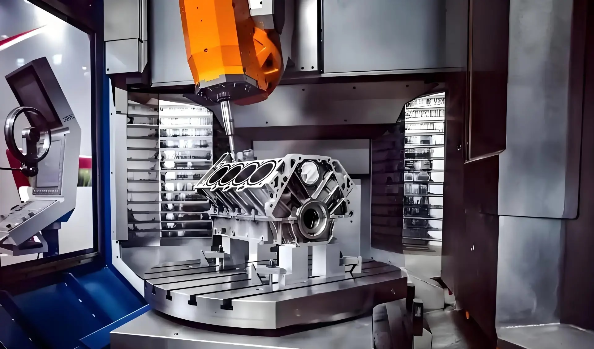
A 5-axis center adds a second rotary axis on top of the first. The tool axis now tilts, which means a ball-nose cutter can stay normal to a curved surface and a short, stiff tool can reach down the side of a deep rib. True simultaneous motion lets the machine blend a compound angle in one pass instead of stair-stepping it.
The gain is not only geometric. Fewer setups means fewer datums, and fewer datums means tolerance stack-up stops compounding. On a part with five critical faces, moving from three setups to one can be the difference between holding ±0.005 mm and chasing it. That is the real argument for 5-axis on complex work, not the machine count.
Material behavior and why it changes the plan
Aluminium 6061-T6 and 7075 cut fast and hold tight tolerances with modest tool wear. They also move. A thin 6061 wall will bow when the clamp is released, so roughing passes are usually left with 0.3–0.5 mm of stock and the finishing pass runs after the part has relaxed. Ignore that and the part measures correctly in the vise and wrongly on the CMM.
Stainless 304 and 316 work-harden. If the tool rubs rather than shears on the first pass, the surface gets harder and the next pass gets worse. The fix is a positive-rake carbide cutter, constant feed per tooth, and never letting the tool dwell. 17-4PH in the H900 condition cuts more cleanly than the annealed grade, but it also eats inserts faster.
Titanium TC4 (Ti-6Al-4V) and Inconel sit at the hard end. They conduct heat poorly, so the cutting edge absorbs temperature that aluminium would have carried away in the chip. Speeds drop, cutting fluid matters more, and tool life is measured in minutes rather than hours. These materials are machinable, but the cost curve is steep and the design should not add features that a cheaper alloy could carry.
Plastics are their own problem. POM and PEEK cut cleanly with sharp, polished tools and high rake. ABS and PC soften with friction heat and tend to smear. Carbon fibre is abrasive and delaminates if the tool lifts at the exit. In all four cases, the material dictates the tool geometry before the geometry dictates the machine.
Where tolerance and surface finish stop being free
A ±0.005 mm callout is achievable on a rigid setup in a stable material. It is not achievable on a 300 mm long unsupported bore, a 0.5 mm wall, or a part held by two clamps on a thin flange. Tolerance is a property of the whole system: machine, tool, fixture, material and thermal state. The drawing states the number; the setup decides whether it is real.
As a rule, the tighter the tolerance the shorter the tool and the more setups you pay for. Reaching ±0.005 mm usually means a finishing pass with light depth of cut, a sharp tool, a warm-up cycle, and a temperature-controlled room. On a 4,000 mm part that requirement becomes a different conversation entirely.
Surface finish follows a similar logic. Ra 1.6–3.2 μm is as-machined and comes off the tool with no extra work. Ra 0.8–1.6 μm needs a controlled finishing pass and a sharp edge. Ra 0.2–0.8 μm means a dedicated finishing strategy, sometimes a smaller stepover, and often a secondary operation such as polishing or lapping.
The trap is specifying the finest finish on every face. A mating bore may need Ra 0.4 μm. A non-contact cover plate does not. Marking only the surfaces that carry a function keeps cycle time and cost where they belong.
How to judge a CNC machining FL supplier
Start with the quote process itself. A supplier that returns a price in a week for a simple bracket is telling you something about how it will handle a change order. A quotation plus a DFM analysis inside 12 hours, with specific notes on wall thickness or tool reach, is a better signal than a low number. The DFM comments show whether anyone actually read the model.
Then ask what the machine list looks like. A shop with only 3-axis mills will quietly quote 5-axis work and fixture it three times. If your part has compound angles, deep ribs or a requirement to hold one datum across five faces, ask directly how many setups are planned and which machine runs the finishing pass.
Inspection is the third question. 100% inspection before shipment, with raw material check, in-process monitoring and a final report, is a documented process. Ask what gets measured, on what equipment, and whether you get the report. On safety-critical parts in aerospace or medical device programs, this matters more than the per-piece price.
Certification scope is the fourth. ISO 9001:2015 covers quality systems. IATF 16949:2016 applies to automotive production. ISO 13485:2016 is the medical device standard, and ISO 27001:2022 covers information security, which is what protects your drawings. A supplier holding all four can serve several of your programs without a separate audit each time.
Finally, distance is a smaller factor than most buyers assume. A part machined overseas and shipped in 3–5 days often beats a local shop quoting three weeks, provided the inspection paperwork travels with it. What you cannot outsource is the clarity of your drawing and the DFM conversation.
Choosing the machine and process for the part
Match the feature to the setup, not the other way around.
| Part feature | Recommended setup | Typical tolerance | Watch out for |
|---|---|---|---|
| Flat plate, features on two faces | 3-axis, two setups | ±0.05 mm | Datum shift between setups |
| Holes around a cylinder | 4-axis with rotary table | ±0.02 mm | Indexing error, chip nesting |
| Compound angle, one setup | 5-axis simultaneous | ±0.005 mm | Tool reach on deep ribs |
| Deep pocket in 4140 | 3-axis, rough then finish | ±0.02 mm | Heat build-up, chip recutting |
| Thin-wall 6061 housing | 5-axis, light finishing pass | ±0.01 mm | Spring-back after unclamping |
| Titanium TC4 bracket | 5-axis, high-pressure coolant | ±0.01 mm | Tool life, edge temperature |
| Long shaft, Ø400 mm table | Mill-turn center | ±0.01 mm | Sag on unsupported length |
| Cosmetic cover, anodized | 3-axis, bead blast + anodize | ±0.1 mm | Blast hiding tool marks |
The short answer
If the part is prismatic and the features sit on two faces, a 3-axis setup is the right call and 5-axis only adds cost. If it has compound angles, deep ribs or five critical faces that must share one datum, pay for the 5-axis setup and skip the re-clamps.
Common questions
Does the location of the shop change the achievable tolerance?
No. Tolerance comes from the machine, the fixture and the material, not the postal code. A 5-axis center in Dongguan holds the same ±0.005 mm as one in Florida if the setup is rigid and the room is temperature-controlled.
What location does change is communication latency and shipping time. If your program needs a same-day DFM discussion, that is a real constraint. If it needs parts in a week, an overseas shop that ships in 3–5 days is often faster than a local backlog.
When is 5-axis the wrong choice?
When the part is a flat plate with holes, or a simple turned shaft. A 5-axis center can make those parts, but you pay for capability you are not using, and a 3-axis mill or a lathe will finish them in less time.
The other wrong case is a part whose geometry is fine but whose volume is huge. Above roughly 10,000 pieces a year, casting or forging plus a light finishing cut usually beats cutting the whole shape from bar stock.
How do I know if a wall is too thin to machine?
A rough working number for aluminium is a wall no thinner than 1 mm over a 20 mm span. Below that, the wall deflects under cutting force and chatters, and the finish degrades even if the dimension holds.
Stainless and titanium need more. A 0.5 mm wall in 316 is possible only with light finishing passes, a supporting fixture, and acceptance that the part may move after unclamping. If the design allows 1.5 mm instead of 0.8 mm, take it.
What causes a part to measure correctly in the vise and fail inspection?
Residual stress. Removing material releases internal stress that was locked in the bar or plate, and the part springs. The effect is largest on thin sections and on cold-drawn or rolled stock.
The standard countermeasure is to rough with 0.3–0.5 mm of stock left, let the part rest, then finish. For very unstable geometry, a stress-relief anneal between roughing and finishing is worth the extra day.
Do surface finishes need a separate supplier?
Not if the shop runs post-processing in house. Anodizing, plating, powder coating, black oxide, bead blasting, tumbling, brushing, polishing and laser marking can all be handled as one flow after machining.
Keeping them together avoids a second handling step and a second set of datum questions. It also means one party is responsible when a cosmetic face comes back with a mark on it.
How much does the drawing itself affect the quote?
A lot. A model with clear GD&T, defined datums and finish callouts on functional faces gets quoted faster and more accurately than one with a blanket tolerance note.
If a face does not mate, seal or slide, do not put a tight tolerance on it. Every tight callout that carries no function adds inspection time and cost without improving the part.
Send the model, get a DFM answer
Upload a STEP file and we return a quotation with free DFM analysis within 12 hours. No minimum order quantity, from one prototype to 10,000+ parts.
12-hour quote100% inspectionNo MOQNDA on request
More from the shop floor
We publish setup notes, tooling trials and inspection data from the factory floor.











