
CNC machining in Sitka: how it actually works
Sitka is a small island city in southeast Alaska, so local machining capacity is limited. This page explains what CNC machining in Sitka really means for engineers and buyers, which parts a machine shop can hold to ±0.005 mm, and when sourcing from a larger facility makes more sense.
Key takeaways
What CNC machining in Sitka actually removes
Every CNC machine does the same basic thing: a spinning cutter follows a toolpath and shears material away. The numerical control part means the path is calculated from your CAD model, so the shape of the part is decided long before the spindle turns. In Sitka, that calculation is identical to what happens in a shop in Seattle or Dongguan.
The variable is the machine, not the math. A three-axis mill moves the workpiece in X, Y, and Z while the tool stays vertical. It is fast, rigid, and cheap to run. Most brackets, plates, housings, and heat sinks never need anything more.
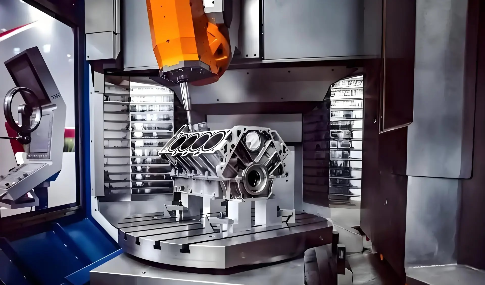
Five-axis machining adds two rotary axes. The tool can tilt and the table can rotate, so the cutter approaches the part from angles a three-axis machine cannot reach. That matters for impellers, turbine blades, medical instruments, and any part with deep undercuts or walls steeper than the tool can safely reach.
There is also a subtler benefit. On a three-axis machine, a part with features on five sides needs five setups. Each setup adds a fixture, a re-clamp, and a fresh chance to lose 0.02 mm. A five-axis center machines those features in one setup, which is why the accuracy gain is often larger than the axis count suggests.
Why ±0.005 mm is a system, not a number
A tolerance is a promise about the spread of a dimension across every part in the run. Reaching ±0.005 mm (±0.0002 in) is not a matter of telling the operator to be careful. The machine, the toolholder, the fixture, the material, and the room temperature all push on that number at the same time.
Thermal drift is the usual culprit. Aluminum expands roughly 23 μm per meter per °C. A 300 mm aluminum part that warms by 3 °C during roughing grows about 20 μm before finishing even starts. Shops that hold tight tolerances either control the room or leave a finishing allowance and cut it after the part has settled.
Fixturing decides how much of that tolerance you actually keep. A part clamped on a single vise jaw will deflect under cutting load. Thin walls move away from the cutter. Deep pockets trap chips that recut and smear the surface.
Surface finish and tolerance travel together. A wall held to ±0.005 mm with a Ra 3.2 μm finish is rarely useful in a sealing or bearing application, so we usually treat the two as one requirement. Finish bands we work to: Ra 0.2–0.8 μm for fine work, Ra 0.8–1.6 μm for typical high-quality parts, and Ra 1.6–3.2 μm as-machined.
Material choice sets the cutting window
The same geometry in 6061 aluminum and 17-4PH stainless behaves like two different jobs. Aluminum cuts fast, throws heat into the chip, and lets you run high spindle speeds. Stainless work-hardens, holds heat at the edge, and punishes a light feed that rubs instead of cuts.
Titanium sits further out. TC4 (Ti-6Al-4V) has low thermal conductivity, so the heat stays in the cutting zone, and the material is chemically reactive at high temperature. Cutters wear quickly, and the process needs generous coolant and conservative depths of cut. Cutting forces are high, so thin unsupported sections are a real risk.
Plastics are their own problem set. POM and PEEK machine cleanly but move with temperature. ABS and PC can gum up a cutter if the chip load is too low. Carbon fibre is abrasive and needs carbide or diamond tooling plus dust control.
For Sitka specifically, material supply is part of the schedule. Bar stock and plate often arrive by barge, so a job that needs a specific temper or thickness may wait on freight before it waits on a machine. Sending your own material to the shop is common, and it works, as long as the stock has enough allowance for cleanup.
What remote sourcing changes for Sitka buyers
Sitka sits on Baranof Island with no road connection to the mainland. That shapes how a machining job runs more than any technical factor does. Tooling, stock, and finished parts move by air or by barge, and weather can add days with no warning.
The practical answer most engineers here use is to split the work. Simple parts, repairs, and fixtures stay local where a machinist can measure the mating component in person. Complex geometry, tight tolerances, and production volumes go to a facility with the right spindle and the right metrology.
That split works because the front end of a job is now digital. A STEP file, a tolerance callout, and a finish spec are enough to start. We return a quotation and a DFM analysis within 12 hours, production can start within 24 hours, and parts ship in 3–5 days. The freight leg is the slow part, not the cutting.
Confidentiality is the other concern that comes up. Uploads are handled as confidential, and an NDA is available on request before drawings are shared. For defense-adjacent or medical work, that step is usually taken first.
When a local shop is the wrong answer
CNC machining is not always the right process, and adding axes does not fix a bad part design. If a feature cannot be reached by any rotating cutter, no machine will produce it. Sharp internal corners are the classic example: a cutter has a radius, so the corner has one too.
Thin, tall walls are another boundary. A 0.5 mm wall on a 40 mm tall aluminum part will deflect, sing, and measure differently every time you touch it. The fix is usually a design change, not a slower feed.
Cost also has a floor. A part that could be stamped, cast, or printed in the thousands is expensive to mill one at a time. CNC earns its place in prototypes, low volumes, tight-tolerance features, and parts where the material or the geometry rules out other processes.
For anything else, the honest answer is to say so early. A DFM review that kills a bad design on day one saves more money than any machining optimization later.
Which machine fits which part
Match the geometry and the tolerance band, not the marketing spec.
| Part feature | 3-axis | 5-axis |
|---|---|---|
| Flat plate, holes on one face | Best fit, lowest cost | Overkill |
| Pockets and slots, one side | Best fit | Unnecessary |
| Five-sided housing | Multiple setups | One setup |
| Impeller or blade profile | Not practical | Required |
| Deep undercut, steep wall | Long tools, chatter risk | Tilted approach |
| ±0.005 mm on stacked features | Setup error adds up | Fewer datum shifts |
| One-off prototype | Fast, cheap | Worth it if geometry is complex |
The verdict
If your part is prismatic and the tolerance is looser than ±0.02 mm, use a local Sitka shop and keep the logistics simple. If it has five-sided geometry, undercuts, or a true ±0.005 mm requirement, send the file to a facility with five-axis capacity and metrology that can prove the number.
Common questions
How tight a tolerance can a five-axis machine actually hold?
On a well-fixtured part in aluminum or stainless, ±0.005 mm is achievable on critical features. That is the tightest band we quote, and it depends on feature size, wall thickness, and how many setups the part needs.
Looser bands cost less and run faster. If a dimension only needs ±0.05 mm, say so on the drawing. Over-tolerancing is one of the most common ways to raise the price of a simple part.
Does part size limit what can be machined?
Yes. We run travels up to 4,000 × 400 × 150 mm on the large machines, plus 750 × 1,150 × 550 mm, 600 × 600 × 600 mm, and compact envelopes down to 500 × 310 × 200 mm. Rotary work uses a Ø400 mm table.
The practical limit is usually not the envelope but the rigidity. A long, thin part that fits the table may still chatter, so the setup has to change.
What file formats and information do you need to quote?
A STEP or IGES model plus a 2D drawing with tolerances, material, finish, and quantity. If you only have a model, send it. We can flag the dimensions that need a tolerance call.
Quotation and a free DFM analysis come back within 12 hours.
Can you work from a sample part instead of a drawing?
Often yes, for reverse engineering. Send the physical part or clear photos with a few key dimensions and we can build the model. Critical fits still need to be measured and confirmed before production.
This is common for replacement parts on older equipment where no drawing survives.
How is quality verified before shipment?
Every order gets 100% inspection before shipment, with raw material checks, in-process monitoring, and a final inspection. Inspection reports are available on request.
Our quality system is certified to ISO 9001:2015, IATF 16949:2016, ISO 13485:2016, and ISO 27001:2022.
Is there a minimum order quantity?
No. We run from a single prototype up to 10,000+ part runs on the same quoting path. Prototype and production parts come off the same machines, so the dimensions you approve are the dimensions you get later.
Quantities above a few thousand usually get a price break because setup is amortized.
Send your part file, get a real answer
A quotation and free DFM analysis come back within 12 hours, and production can start within 24 hours.
12-hour quote±0.005 mm100% inspectionNo MOQ
More from the shop floor
We publish setup notes, tooling trials and inspection data from the factory floor.











