
CNC machining LA: how parts get made and what to check first
This page explains what actually happens when a Los Angeles team sends a design out for CNC machining LA work: how the cut is planned, where tolerance is lost, and which decisions change the price. It is written for design engineers and buyers who need to judge a quote, not just accept it.
Key takeaways
What happens at the cutting zone
A CNC machine does not cut a shape. It removes material along a path, and the accuracy of that path depends on the whole loop: spindle, tool holder, tool, workpiece, fixture and machine frame. When a Los Angeles team asks for CNC machining LA work on an aluminum housing, the drawing may call out ±0.005 mm on two bores. That number is achievable, but it is not produced by the control software alone. It is produced by a short, stiff tool held in a clean taper, cutting a material that does not move much under load.
Heat is the first thing that moves the number. Aluminum 6061 conducts heat away quickly, so the part stays close to size. Stainless 316 and Ti-6Al-4V do not. They push heat into the tool edge, the tool wears, and the effective diameter drifts. A machinist compensates by slowing the feed, adding coolant, and taking a light finishing pass. None of this is visible on the drawing, but it decides whether the bore lands inside the band.
Tool deflection sets the floor on internal corners. A Ø6 mm end mill hanging 40 mm out of the holder will bend under side load. The corner it leaves is not the corner on the drawing. Roughing with a larger tool and finishing with a short, stubby tool is the usual answer. If a pocket has a 3 mm internal radius and sits 50 mm deep, the shop needs a long, thin tool, and the tolerance has to open up. That is a geometry problem, not a skill problem.
Clamping is the third mover. A thin wall pushed by a vise will spring back after the load releases. The part measures correctly on the machine and incorrectly on the CMM. Soft jaws, low-pressure clamps, and support material left in place until the last operation all reduce this. When a buyer asks why a quote is higher than expected, the answer is often that the part needs three setups instead of one.
- 1Rigid setup firstShort tool, minimal overhang, clean holder taper.
- 2Light finishing pass0.1–0.2 mm radial cut to control size and finish.
- 3Stable temperatureLet the part normalize before final measurement.
Why setup count matters more than cycle time
A three-axis machine holds a part in one orientation. Every new face needs the part released, turned, and clamped again. Each of those steps adds a small positional error that stacks on the last one. For a bracket with features on four sides, that is four setups and four chances to drift. A 5-axis center reaches the same faces by rotating the table and the spindle, so the part stays clamped. The datum never changes.
This is the real value of 5-axis work on complex parts. It is not about cutting faster. It is about keeping one datum through the whole operation. On a part with angled ports, undercuts, or a contoured surface that meets a flat face at a tight angle, that single datum removes a whole class of error. The tolerance on the angled feature no longer depends on how well the operator re-indicated the part.
For simple prismatic parts, 5-axis is wasted money. A flat plate with holes and a pocket runs fine on a three-axis mill, and the shop can put more spindles on it. The decision rule is straightforward: count the number of distinct directions the tool must approach from. One or two directions means 3-axis. Four or more, or any curved surface that wraps around the part, means 5-axis.
Fixtures also cost time. A dedicated soft-jaw set for a 200-part run pays for itself. For a single prototype, the shop will use a generic vise and accept a slightly longer cycle. Buyers who send a fixture design with the drawing sometimes save a setup, but only if the fixture matches the machine table. Ask before assuming.
- 1Count tool approach directionsOne or two directions: 3-axis is enough.
- 2Keep one datum5-axis avoids re-indicating angled features.
- 3Match fixture to tableA fixture that does not fit costs more than it saves.
Material choice sets the practical tolerance band
The material on the drawing decides how tight the shop can realistically hold. Aluminum 6061 and 7075 cut cleanly and hold ±0.005 mm on stable features. Stainless 303 machines well but work-hardens if the feed is too light, so the finishing pass has to bite. Stainless 316 is gummier and moves more under heat. Titanium Ti-6Al-4V needs sharp tools, low surface speed, and more coolant, and it will still spring during thin-wall cuts.
Plastics behave differently again. POM and PEEK hold size well but expand with temperature. ABS and PC are soft and can smear rather than cut. A ±0.05 mm band is realistic on POM; ±0.005 mm is not. When a drawing carries the same tight tolerance across an aluminum body and a plastic cover, the shop will flag the plastic feature and ask for relief.
Inconel and magnesium sit at the two ends of the difficulty range. Inconel work-hardens fast and wears tools, so the shop plans for more tool changes and a slower cycle. Magnesium AZ31B and AZ91D cut easily but need chip control because fine magnesium dust is a fire risk. Neither material is a reason to refuse a job, but both change the process plan and the price.
Surface finish and tolerance interact. A Ra 0.2–0.8 μm finish usually needs a separate finishing pass or a polishing operation, and polishing removes material. If a bore has both a tight diameter and a fine finish, the shop must leave enough stock for the polish and still land inside the band. Calling out Ra 0.8–1.6 μm from the cutter is often enough and costs less.
- 1Aluminum holds tight bands6061 and 7075 are the easiest route to ±0.005 mm.
- 2Stainless needs a real cutToo light a finishing pass work-hardens the surface.
- 3Plastics need looser bandsThermal growth makes ±0.005 mm unrealistic on most plastics.
Finishing changes dimensions, so order the operations
Anodizing grows the part. A clear or color anodize layer is thin, but hardcoat anodize can add several micrometres per surface, and that changes a bore diameter. If a bore must mate with a shaft after anodizing, the shop has to machine it undersize by the expected growth, or mask the bore so it is not coated. Both are normal, and both need to be stated before the run starts.
Plating behaves the same way. Electroless nickel, zinc, silver and gold all add a layer. On a threaded feature, plating can make a nut bind. The usual fix is to cut the thread to a pre-plate size or mask it. On a press-fit bore, the same logic applies. A drawing that specifies the final plated dimension is easier to machine than one that specifies the machined dimension and leaves the plating thickness to guesswork.
Bead blasting, tumbling, brushing and polishing change the surface but not the nominal size, unless the polish is aggressive. Laser marking does not change size at all, but it needs a minimum character height of 1.5 mm to stay readable. A part number etched at 0.8 mm will look fine in the CAD file and illegible on the shop floor.
The sequence matters as much as the operation. Machining, then deburring, then finishing, then final inspection is the safe order. If inspection happens before anodizing, the measured size is not the delivered size. GreatLight runs 100% inspection before shipment, with raw material checks and in-process monitoring, so the final number on the report reflects the finished part.
- 1State the final dimensionSpecify whether the tolerance applies before or after coating.
- 2Mask critical featuresThreads and press fits often need masking.
- 3Mark at 1.5 mm or largerSmaller laser text will not read clearly.
What to send, and what comes back
A useful RFQ package has four things: a 3D model, a 2D drawing with tolerances and finish callouts, the material grade, and a short note on what the part does. The function note is the most underused item. If a bracket only locates a cover, a ±0.1 mm band is fine. If a bore carries a bearing, the band has to be tight. The shop cannot tell the difference from geometry alone.
GreatLight returns a quotation and a free DFM analysis within 12 hours. The DFM report flags features that are hard to machine, suggests tolerance relief where it does not affect function, and notes where a design change would cut cost. Production can start within 24 hours of approval, and parts ship in 3–5 days. Historical late-delivery probability is below 2%.
For Los Angeles teams, the practical question is not where the machine sits. It is whether the shop can hold the tolerance, document the inspection, and protect the design. GreatLight holds ISO 9001:2015, IATF 16949:2016, ISO 13485:2016 and ISO 27001:2022 certifications, which cover quality management, automotive, medical devices and information security. Uploads are handled as confidential, and an NDA is available on request.
There is no minimum order quantity. A single prototype and a 10,000-part run go through the same quoting process. That matters for engineers who need to prove a design before committing to tooling. The first article can be measured and reported before the rest of the run starts.
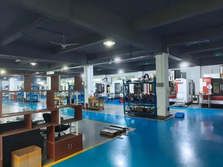
Capacity is the last piece. GreatLight runs 127 high-precision CNC machines across three wholly-owned plants covering 7,600 m², with 150 technicians. The fleet includes 16 simultaneous 5-axis machining centers, 12 four-axis mills, 27 three-axis machines and 16 mill-turn centers. Maximum processing size is 4,000 mm, and the largest travel is 4,000 × 400 × 150 mm. A Ø400 mm rotary table handles round parts that need indexing.
- 1Model plus drawing plus functionThe function note lets the shop relax non-critical tolerances.
- 2Ask for the DFM reportIt shows which features drive the price.
- 3Check the certification scopeMatch the certificate to your industry, not just the logo.
Which process route fits your part
Pick the row that matches the geometry, not the one that sounds most capable.
| Part feature | Best route | Why |
|---|---|---|
| Flat plate, holes on one face | 3-axis mill | One setup, low cost per part |
| Features on four sides | 4-axis or 5-axis | Part stays clamped, one datum |
| Angled ports and contoured faces | 5-axis simultaneous | Tool reaches without re-fixturing |
| Round part with cross holes | Mill-turn center | Turning and milling in one setup |
| Thin wall, tight tolerance | 3-axis with soft jaws | Low clamp pressure, light finish pass |
| Hardcoat anodized bore | Machine undersize or mask | Coating growth changes the diameter |
| Laser-marked part number | Any route, 1.5 mm min | Smaller text is not readable |
| Single prototype, no fixture | 3-axis with generic vise | Fixture cost is not recovered |
The trade-off in one line
If your part has features on four or more sides, pay for 5-axis and keep one datum. If it is a flat plate with holes, keep it on 3-axis and spend the money on inspection instead.
Questions engineers ask next
Can you hold ±0.005 mm on every feature of a part?
No, and no shop should promise that. A ±0.005 mm band is realistic on stable features in aluminum or brass, cut with a short rigid tool on a machine that is warm. On thin walls, deep pockets, long tools or heat-sensitive materials, the band has to open up. The DFM report will say which features can hold tight and which cannot.
The useful approach is to mark only the features that need the tight band. A drawing with ±0.005 mm on all dimensions costs more and does not improve the part.
How does 5-axis machining change the price on a simple part?
It usually raises it. A 5-axis center costs more per hour, and a simple prismatic part does not need the extra reach. The exception is a part that would otherwise need three or four setups on a 3-axis machine. When setup time is high, 5-axis can be cheaper even on a moderately simple part.
What tolerance is realistic for plastic parts?
For POM, PEEK and similar engineering plastics, ±0.05 mm is a reasonable target on stable features. ABS and PC are softer and can smear, so ±0.1 mm is more honest. Plastics also grow with temperature, so a part measured right off the machine may not match the same part measured after it cools. State the measurement temperature if the tolerance is tight.
Do you need a 2D drawing, or is a 3D model enough?
A 3D model alone leaves tolerance and finish open to interpretation. Send both. The model defines geometry, and the drawing defines the bands, the datum scheme, the finish callouts and any masking requirements. If the drawing does not exist yet, the DFM team can work from the model and flag the decisions that need to be made.
How are inspection results reported?
Every part is inspected before shipment, with raw material checks, in-process monitoring and a final inspection. Reports are available on request, and they reflect the finished part after any coating or plating operation. If your industry requires a specific report format, say so at the quoting stage.
Can you start production before an NDA is signed?
We can quote from a model and drawing without one, and we treat uploads as confidential. For detailed design files, an NDA is available on request and is the better route. Either way, the files are not shared outside the project.
Send the drawing and get a DFM report back
Upload your model and drawing, and we will return a quotation with a free DFM analysis within 12 hours. No minimum order quantity, from one prototype to a 10,000-part run.
12-hour quote100% inspectionNo MOQNDA on request
More from GreatLight
We publish setup notes, tooling trials and inspection data from the factory floor.











