
CNC Machining Nevada: How the Process Actually Works
A working explanation of what drives tolerance, cost and lead time when you source machined metal parts for Nevada programs. Written for design engineers and sourcing teams who need to judge a quote, not just collect one.
In this article
- 1
- 2
- 3
- 4
- 5
- 6
- 7
Key takeaways
What CNC machining Nevada really means for a buyer
When an engineer searches for CNC machining Nevada, the phrase usually means one of two things: a supplier physically located in the state, or a supplier who can serve a Nevada program without friction. The second case is far more common. Most parts designed in Reno, Las Vegas or Carson City are cut somewhere else, then shipped. What matters is not the zip code of the spindle. What matters is whether the shop can hold the tolerance you called out, document it, and repeat it on the next order.
We run three wholly-owned plants with 127 high-precision CNC machines, including 16 simultaneous 5-axis machining centers. Parts ship in 3–5 days once production starts, and production can begin within 24 hours of a released order. For a Nevada buyer this means the physical distance is a logistics detail, not a technical limit. The engineering conversation is identical whether the mill sits in Sparks or in Dongguan.
The reason location feels important is legacy. Twenty years ago, a machined part needed a local shop because drawings traveled by fax and a bad setup meant a week lost. That constraint is gone. Today a STEP file, a tolerance callout and a material spec carry all the information a shop needs. The real risk has moved to something else: unclear callouts that two shops interpret differently.
- 1Drawings travel digitallyA 3D model plus a tolerance table replaces the site visit.
- 2Distance affects freight, not accuracyThe spindle does not know which state the customer is in.
- 3Ambiguity is the real cost driverTwo shops quoting different prices usually read the print differently.
How the cutting process removes metal and where error enters
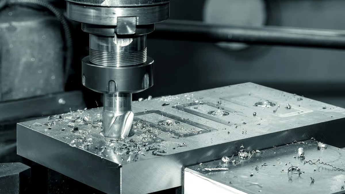
CNC machining is subtractive. A rotating cutter removes material along a programmed path, and the finished surface is the leftover shape. Every source of error enters through that loop: the machine's positioning, the tool's deflection, the workpiece's movement under clamping force, and thermal growth as the spindle warms. None of these are random. Each has a signature you can design around.
Tool deflection is the one engineers underestimate most. A Ø6 mm end mill hanging 60 mm out of the holder will bend under cutting load. On a finishing pass at 0.2 mm radial depth that bend may be a few micrometers. On a roughing pass at 3 mm radial depth in 4140 steel it can be 0.05 mm or more. The part springs back after the cutter passes, so the wall you measure is not the wall the tool cut.
Thermal drift matters on long cycles. A spindle running for four hours grows, and the Z axis effectively moves. Shops compensate by warm-up routines, in-process probing, or by finishing critical features late in the cycle when the machine has reached steady state. If your part has a ±0.005 mm bore and a 40-minute cycle, ask how the shop handles drift. The answer tells you more than the machine list.
Clamping is the quiet third source. Thin walls, ring sections and long slender parts distort when a vise closes on them. Soft jaws machined to the part profile, or fixturing on a sacrificial tab, removes most of it. A part that measures perfectly on the machine and out of tolerance after unclamping was clamped too hard.
- 1Deflection scales with tool overhangKeep the flute length close to the cut depth when the print is tight.
- 2Warm-up before finishingA cold spindle and a warm spindle do not cut the same part.
- 3Clamping force is a variableDistortion shows up after release, not during the cut.
Why 5-axis changes the setup count, not just the shape
A 3-axis mill holds the part still and moves the cutter in X, Y and Z. A 5-axis center adds two rotary axes, so the tool can approach a face from an angle without the operator unclamping and re-fixturing. That is the whole benefit, and it is a cost benefit more than a geometry benefit. Fewer setups mean fewer chances to lose datum, and datum loss is the root cause of most out-of-tolerance features on multi-face parts.
Consider a housing with bores on four sides. On a 3-axis machine that is four or five setups, each with its own dial-in, and the position of bore B depends on how well the operator re-established datum after flipping the part. On a 5-axis center with a Ø400 mm rotary table, it is one setup. The bores stay in the same coordinate frame for the whole cycle.
The second gain is tool access. Undercuts, deep pockets with drafted walls and blended fillets that would need a long, flexible cutter on a 3-axis machine can be reached with a short, stiff tool on a trunnion. Stiff tool means less deflection, which means the surface finish and the wall position both improve. Ra 0.8–1.6 μm becomes routine rather than a special request.
The tradeoff is programming and cycle time. A 5-axis toolpath is slower to program and the machine moves more slowly through the same volume. For a simple plate with holes on one face, 3-axis is faster and cheaper. For a complex part with features on five faces, 5-axis usually wins on total cost because the setup savings dominate.
- 1One setup beats fiveDatum error compounds every time the part is reclamped.
- 2Short tools cut straighterRotary axes let a stiff tool reach features a long tool cannot.
- 3Know when not to use itFlat plates with one working face belong on a 3-axis machine.
Tolerance, surface finish and the cost curve between them
Tolerance and finish are not free. Each step tighter costs more, and the cost curve is not linear. Moving from ±0.1 mm to ±0.05 mm is routine. Moving from ±0.05 mm to ±0.005 mm changes the process: you need temperature control, a warm machine, a finishing pass with a fresh tool, and often a CMM check rather than calipers. That last step costs more than the first two combined.
Surface finish follows the same pattern. As-machined surfaces run Ra 1.6–3.2 μm. A careful finishing pass reaches Ra 0.8–1.6 μm. Below that, Ra 0.2–0.8 μm, you are usually looking at a secondary operation such as lapping or fine polishing, or a very light finishing pass with a small stepover. The surface is measurable, so specify it where it matters: sealing faces, bearing bores, sliding surfaces. Leave the rest as-machined.
A common mistake is applying a blanket tolerance note to the whole drawing. The shop then has to hold every dimension to ±0.005 mm, including the ones that never touch another part. That inflates the quote and adds inspection time for features that carry no function. Call out tight tolerance only on mating and locating features.
The same logic applies to material. Aluminum 6061 and 7075 cut cleanly and hold tight tolerance well. 316L stainless work-hardens and needs slower feeds. Ti-6Al-4V and Inconel generate heat at the cutting edge and wear tools fast, so cycle time and tool cost both rise. None of this is a reason to avoid the material. It is a reason to know why the quote looks the way it does.
- 1Tight only where it functionsBlanket ±0.005 mm on a whole drawing buys inspection, not fit.
- 2Match finish to the interfaceSealing and bearing surfaces need Ra; cosmetic ones rarely do.
- 3Hard alloys cost in timeTitanium and Inconel wear tools and slow the spindle.
Inspection, documentation and what a certificate does not prove
A certificate tells you the shop's quality system was audited. It does not tell you the part in the box is correct. Those are two different claims, and mixing them up is how buyers get surprised. ISO 9001:2015 covers the process. IATF 16949:2016 adds automotive-specific discipline. ISO 13485:2016 addresses medical devices, and ISO 27001:2022 covers information security, which matters when your files are customer drawings under NDA.
What proves the part is a measurement record. We inspect 100% of parts before shipment, with raw material check, in-process monitoring and final inspection. Reports go out on request. For a first article, that report should list the nominal, the tolerance band, the measured value and the instrument used. If a shop cannot show you which instrument produced a number, the number is a claim, not data.
Metrology has to match the tolerance. Calipers read to about ±0.02 mm on a good day, which is four times wider than a ±0.005 mm band. If the print calls for ±0.005 mm, the check needs a micrometer, a bore gauge or a CMM. Ask what the shop will use. A shop that answers with the instrument name and not just the word 'QC' is the one to keep.
The last piece is traceability. Material certificates, heat lot numbers and revision control on the drawing are what let you investigate a problem six months later. This costs almost nothing to set up and saves a lot when something goes wrong.
- 1Certification is not inspectionOne audits the system, the other checks the part.
- 2Match instrument to toleranceCalipers cannot verify a ±0.005 mm bore.
- 3Keep the paper trailMaterial certs and drawing revisions answer future questions.
Choosing the right setup for a Nevada machining program
Match the part geometry and tolerance to the process before you request a quote.
| Part situation | Recommended process | Why it fits |
|---|---|---|
| Flat plate, holes on one face | 3-axis milling | One setup, fast cycle, lowest unit cost |
| Housing with bores on 4+ faces | 5-axis simultaneous | One setup keeps all features in one datum |
| Turned shaft with milled flats | Mill-turn center | Turning and milling finish in one clamping |
| Tolerance tighter than ±0.01 mm | Finish pass + CMM report | Warm machine and measured data, not position readout |
| Sealing or bearing face | Ra 0.2–0.8 μm finishing | Surface finish drives seal life, not just tolerance |
| Thin wall under 2 mm | Soft jaws or tab fixturing | Prevents clamping distortion after release |
| Prototype, 1 to 50 pieces | No MOQ, 5-axis prototype run | Same process as production, no tooling investment |
| Titanium or Inconel part | Slow-feed 5-axis with carbide | Hard alloys need lower speed and fresh edges |
The honest tradeoff
If your part has features on five faces and a tolerance under ±0.01 mm, pay for 5-axis and a CMM report. If it is a flat plate with holes, use 3-axis and save the money for the parts that need it.
Common questions
Do you need a Nevada address to serve a Nevada program?
No. Files travel digitally and parts ship by air or ground freight. What a program needs is a shop that holds the tolerance, documents it and repeats it on the next order.
We run three wholly-owned plants with 127 CNC machines and ship parts in 3–5 days once production starts. The engineering review is the same regardless of the customer's location.
How tight a tolerance can you actually hold?
±0.005 mm (±0.0002 in) on called-out features, with the right process and inspection. That is not a blanket number for the whole part.
Features outside the tolerance band stay at normal machining tolerance, which keeps cost and lead time down.
What surface finish comes standard?
As-machined parts run Ra 1.6–3.2 μm. A finishing pass reaches Ra 0.8–1.6 μm, and Ra 0.2–0.8 μm is available where a sealing or bearing surface needs it.
Specify finish only on the faces that function. Cosmetic surfaces rarely need better than as-machined.
Which materials do you machine most often?
Aluminum 6061, 7075 and 6082, stainless 303, 304, 316L and 17-4PH, steels including 4140 and 4340, copper and brass alloys, titanium grades TA2 and TC4, Inconel, and engineering plastics such as POM, PEEK and PC.
Hard alloys such as Inconel and Ti-6Al-4V cut slower and wear tools faster, so cycle time rises. That is a process fact, not a markup.
What is the minimum order quantity?
There is no minimum. We run from a single prototype to 10,000+ part runs on the same process.
Because the prototype and the production run use the same machines and fixtures, the first article data carries forward.
How do you handle confidentiality?
Uploads are secure and confidential, and we operate under ISO 27001:2022 for information security. An NDA is available on request.
Raw material certificates and drawing revisions are kept so a problem can be traced months later.
Send the drawing, get a real answer
Quotation and free DFM analysis within 12 hours. Tolerance, material and finish reviewed by the engineer who will run the job.
12-hour quoteFree DFM analysis100% inspection
More from the shop floor
We publish setup notes, tooling trials and inspection data from the factory floor.











