
CNC Milling 101: How Material Removal Actually Works
CNC milling 101 is the study of one thing: a spinning cutter moving through metal along controlled axes. This guide covers the mechanics, the setups, and the limits. You will finish able to judge whether a part belongs on a mill, and which one.
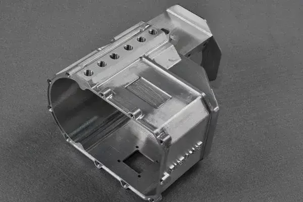
What Happens Where the Tool Meets the Metal
A milling cutter is a cylinder of hardened steel with teeth around its edge. The spindle spins it, the table moves the workpiece under it, and each tooth takes a small chip. The chip is where the work happens. If the tooth rubs instead of cutting, you get heat, work hardening, and a short tool life.
Chip load is the thickness of material each tooth removes per revolution. Too small a chip load and the edge burnishes the surface. Too large and the tool deflects or snaps. On aluminium, a common range is 0.05–0.15 mm per tooth for a 10 mm end mill. On 304 stainless, that drops to roughly 0.03–0.08 mm.
Spindle speed and feed rate are linked to chip load by one relationship: feed rate equals spindle speed times number of teeth times chip load per tooth. Change the spindle speed alone and the chip gets thinner, not the feed per tooth. That is why operators set feed and speed together, not one at a time.
Climb milling and conventional milling describe which way the tooth enters the cut. Climb milling throws the chip behind the cutter and pulls the workpiece into the tool. On a machine with backlash-free ball screws, climb milling gives a better finish and longer tool life. On a worn manual mill, it can grab the part.
Heat is the real enemy. Roughly 80% of the heat from cutting leaves with the chip. If your chips come off blue and thin, the tool is rubbing, not cutting. If they come off silver and thick, the cut is healthy.
Three, Four, and Five Axes in Plain Terms
A three-axis mill moves the table in X, Y, and Z. The tool always points straight down. This is the workhorse setup, and it covers most prismatic parts: plates, housings, brackets, manifolds with features on one face or a few faces reached by repositioning the part.
A four-axis mill adds rotation around one axis, usually A. The part turns while the tool stays put. This lets you cut a cylinder, drill holes around a shaft, or machine four faces of a part without re-fixturing. For round or shaft-like parts, four-axis is often the fastest route.
A five-axis mill adds two rotary axes, so the tool can approach the part from almost any direction. The payoff is not speed. It is access. Undercuts, deep pockets with curved walls, and features that would need three separate setups on a three-axis machine can be cut in one.
Five-axis also lets you keep a short, stiff tool. Instead of hanging a long end mill into a deep cavity, you tilt the head and reach the floor with a stubby cutter. Shorter tool means less deflection, and less deflection means tighter tolerance. That is the real reason to pay for five-axis.
Simultaneous five-axis is different from 3+2 positioning. In 3+2, the rotary axes lock and the machine cuts in three axes. In simultaneous, all five move at once. Simultaneous is harder to program and slower to verify, so use it only when the geometry demands it.
Fixturing, Workholding, and Why Parts Move
A part that moves mid-cut is scrap. Workholding is where most beginner jobs fail, not the cutting parameters. A vise with 2 mm of jaw contact on a 100 mm part will lift under a heavy cut. Clamp on the stock, not on the finished surface, and keep the part as low in the jaws as the geometry allows.
For thin plates, vacuum tables or a sacrificial backing plate beat clamps. A 1.5 mm aluminium plate clamped at two edges will chatter in the middle. Supported across its whole face, it cuts clean. The rule is simple: support the part where the tool pushes.
Zero-point systems and soft jaws cut setup time on repeat work. A soft jaw machined to the part profile holds a complex shape without distortion. On a run of 200 parts, the minutes saved per setup add up faster than any spindle speed increase.
Tabs and bridges hold a part that would otherwise come free during the last pass. Leave 0.5–1.0 mm tabs, then cut them by hand. It sounds crude. It is standard practice on production floors.
For long parts, we use 4,000 × 400 × 150 mm travels on the largest machines. Anything beyond that needs a different plan, not a bigger clamp.
Material Behavior Changes the Whole Plan
Aluminium 6061 cuts freely and is the default for prototypes. It machines at high spindle speeds, holds tolerance well, and anodizes cleanly. 7075 is stronger but gummier; it needs sharper tools and a more rigid setup, and it does not anodize to the same cosmetic standard.
Stainless 304 work hardens the moment a tool rubs. Keep the chip load up, never dwell in the cut, and use a fresh edge. 316L behaves similarly but is the standard for medical and food-contact parts. 17-4PH machines better in the annealed state, then gets heat treated afterward.
Titanium Ti-6Al-4V (TC4) has low thermal conductivity, so heat stays in the tool. Cutting speeds drop to roughly one third of aluminium, and coolant or high-pressure air becomes mandatory. Inconel is worse. Both are machinable, but they punish an aggressive feed.
Plastics are the opposite problem. POM and PEEK cut cleanly but melt if the tool dwells. ABS and PC need sharp, polished flutes and air blast rather than flood coolant. Carbon fibre eats carbide, so use diamond-coated tooling and extract the dust.
Magnesium AZ31B and AZ91D cut fast and light, but the chips burn. Never use water-based coolant on magnesium. The chips must be kept dry and removed from the machine.
Tolerance, Finish, and What You Can Actually Hold
Tolerance is a claim about the whole part, not one feature. A shop can hold ±0.005 mm on a 20 mm bore in a rigid setup. The same shop cannot hold that across a 500 mm thin-wall part, because thermal growth and clamping force move the material more than the tool does.
Surface finish comes from a combination of tool radius, feed per tooth, and spindle stability. Ra 0.8–1.6 μm is a normal as-machined finish for aluminium with a sharp cutter. Ra 0.2–0.8 μm needs a finishing pass with a small stepover, or a secondary operation.
Dimensional inspection is not the same as surface inspection. Calipers check a diameter. They do not tell you if the bore is round or if the wall has a taper. For critical features, use a CMM or a bore gauge. Reports are available on request.
Measurement uncertainty matters. If your tolerance is ±0.01 mm and your micrometer reads to 0.001 mm, you are fine. If the tolerance is ±0.005 mm, you need a controlled-temperature room and a gauge with known calibration. Otherwise you are guessing.
The practical rule: design the loosest tolerance the function allows. Tightening a tolerance that does not need it adds cost, adds inspection time, and adds scrap risk.
Which Setup Fits Which Part
Match the geometry to the machine before you request a quote.
| Part feature | Best setup | Why | Watch out for |
|---|---|---|---|
| Flat plate, holes on one face | 3-axis | Fastest cycle, simple fixture | Thin plate chatter |
| Shaft with cross holes | 4-axis | One setup, no re-fixturing | Long tool overhang |
| Impeller, bladed disc | 5-axis simultaneous | Curved surfaces in one pass | Programming and verification time |
| Deep pocket, curved wall | 5-axis 3+2 | Short rigid tool reaches floor | Rotary table clearance |
| Box with 5 open faces | 5-axis 3+2 | Fewer setups, tighter position | Fixture access to all faces |
| Ø400 mm round flange | 4-axis with rotary table | Continuous rotation, no indexing | Table load limit |
| 4,000 mm long beam | Large 3-axis gantry | Full length in one setup | Straightness over the span |
The Short Version
If the part is prismatic and the features face one direction, use 3-axis and save the money. If it is round, or the features wrap around it, 4-axis is the fastest route. If the geometry is curved in three dimensions or the part needs five faces in one setup, pay for 5-axis. Everything else is a workholding problem in disguise.
Questions Engineers Ask Next
How deep can a CNC mill cut in one pass?
It depends on the tool diameter, the material, and the rigidity of the setup. A 10 mm carbide end mill in aluminium can take 5–10 mm of axial depth at a reduced radial width. In 304 stainless, that drops to roughly 1–2 mm per pass.
Deep slots are usually cut in multiple passes with a smaller radial engagement, not one heavy plunge. If the tool squeals or the chips turn blue, the pass is too heavy for the setup.
Is CNC milling suitable for prototypes?
Yes, and it is often the fastest route to a functional prototype. There is no minimum order quantity, so one part is a valid job. A prototype in aluminium can be machined from bar stock and inspected before you commit to a production tool.
For plastic prototypes, milling gives better mechanical properties than most 3D printing processes. For very complex internal channels, additive may win. The choice depends on the geometry, not on the process name.
What is the difference between 3-axis and 5-axis milling?
A 3-axis machine moves the tool in X, Y, and Z only, so the tool always points down. A 5-axis machine adds two rotary axes, letting the tool approach the part from nearly any angle.
The practical result is fewer setups and better access. Five-axis also lets you use a shorter, stiffer tool on deep features, which improves tolerance. It is not automatically faster per part.
Can CNC milling produce a polished surface?
Machining leaves tool marks. To remove them, add a secondary finishing operation: bead blasting, tumbling, brushing, or polishing. These are standard steps and can be quoted with the machining.
For a mirror finish on aluminium, polishing after machining is the usual path. For a uniform matte look, bead blasting is faster and cheaper.
What tolerance should I put on a drawing?
Put the loosest tolerance the function allows. A general tolerance block of ±0.1 mm for non-critical features and a tighter callout only on the features that mate or seal.
Tightening every dimension on a drawing does not improve the part. It raises cost, adds inspection time, and increases the chance that a good part gets rejected.
How do I know if my part should be milled or turned?
If the part is mostly cylindrical and symmetric around one axis, turning is usually faster and cheaper. If it is prismatic, or has features on multiple faces, milling is the better fit.
Many parts need both. A mill-turn center cuts the round features and the flat faces in one setup, which avoids the position error that comes from moving a part between two machines.
Send the Drawing, Get a Real Answer
Upload a STEP file and we will return a quotation with a DFM analysis, usually within 12 hours. One part or 10,000. No minimum order quantity.
12-hour quote100% inspectionNo MOQ
More Machining Notes
We publish setup notes, tooling trials and inspection data from the factory floor.











