
CNC Milling: Precision Metal Cutting Explained
This page covers how CNC milling precision metal cutting works, where accuracy actually comes from, and which part features push a job toward 5-axis work. It is written for design and manufacturing engineers who need to judge a quote, a tolerance callout, or a process change.
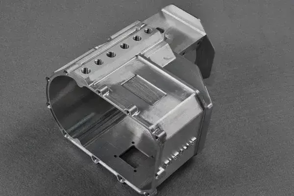
What CNC milling precision metal cutting does at the edge
A CNC mill holds the workpiece and spins a multi-tooth cutter. Each flute takes a small bite, called chip load, and shears metal away. The control moves the tool along a programmed path, so the shape comes from motion rather than from a form tool. That is the core idea behind CNC milling precision metal cutting: the machine repeats a path, and the path decides geometry.
Chip load is the number that matters most. It is feed per tooth, not feed per revolution. A 10 mm three-flute carbide end mill running at 3,000 rpm and 900 mm/min feed takes 0.10 mm per tooth. Drop to 0.02 mm per tooth and the tool rubs instead of cutting. Heat goes into the edge, the edge wears, and the surface turns smeared.
Cutting speed is set by the material, not by the operator's mood. Aluminium 6061 runs fast, often 300–600 m/min surface speed with carbide. Stainless 316 and 17-4PH run far slower, commonly 60–120 m/min, because they work-harden at the cut. Titanium TC4 sits lower still. Spindle speed follows from surface speed divided by tool diameter.
Radial and axial depth of cut control how much of the flute is engaged. Full-width cuts in a slot load the tool heavily and push deflection up. Trochoidal paths take 5–10% radial engagement at higher feed, which keeps radial cutting forces low and lets the same cutter clear a deep pocket without chatter.
Climb milling is the default on modern machines. The cutter tooth enters at maximum chip thickness and exits at zero, which pushes the workpiece away from the tool and reduces rubbing. Conventional milling still has a place on rough castings with hard surface scale, where the entry shock would chip a carbide edge.
- 1Chip loadFeed per tooth. Too low rubs, too high breaks edges.
- 2Surface speedSet by material: aluminium fast, stainless and titanium slow.
- 3EngagementRadial and axial depth decide cutting force and chatter risk.
- 4Climb millingStandard for finish passes on clean stock.
Where the last 0.01 mm of precision metal cutting comes from
Machine accuracy is only the starting point. A machine that positions to ±0.005 mm still produces a bad part if the setup moves. Thermal growth is the usual suspect. A spindle running for two hours grows, and a 100 mm aluminium part can shift several micrometres between the first and last cut. Shops that hold tight tolerances warm up spindles and cut in a temperature-controlled bay.
Tool deflection is the second cause. A long, thin end mill bends under side load. Deflection scales with the cube of length over diameter, so a cutter hanging 60 mm out of a 6 mm collet is roughly 1,000 times more flexible than the same cutter held short. Reach into a deep pocket and you buy reach with accuracy.
Clamping is the third. Vise jaws, soft jaws, and fixture plates all distort thin parts. A 3 mm wall clamped at 4,000 N will spring back when released, and the measured part no longer matches the cut part. Light clamping, support under the cut, and stress-relieved stock are the standard countermeasures.
Tolerance stack-up is the fourth. A ±0.05 mm position tolerance on a hole, a ±0.05 mm datum shift, and a ±0.02 mm perpendicularity error combine. The hole can sit 0.12 mm from nominal in the worst case. Engineers who specify each callout independently often find the assembly will not close even though every individual feature passed inspection.
- 1Thermal driftWarm up spindles and control the room temperature.
- 2Tool deflectionKeep length-to-diameter ratio low; use stub cutters.
- 3Clamping distortionThin walls spring back after the vise opens.
- 4Stack-upIndependent callouts can still miss the assembly.
How the workpiece metal changes the cut
Aluminium 6061 and 7075 cut freely and hold good finish. 7075 is stronger and machines almost as well, though it is more prone to distortion in thin sections. 2024 is tougher and more corrosion-sensitive, so it usually needs anodizing. Cast aluminium ADC12 machines well but can hide porosity that only shows after the skin is removed.
Stainless 303 is the free-machining grade and the easiest of the 300 series. 304 and 316 work-harden quickly. Light passes with a sharp edge and a steady feed keep the cut under the hardened layer. 17-4PH in the H900 condition is hard enough to demand carbide and rigid setups; in the annealed condition it cuts closer to 304.
Titanium TC4, also written Ti-6Al-4V, has low thermal conductivity. Heat stays at the edge instead of leaving with the chip. Cutting speeds drop to roughly 40–70 m/min, coolant flow has to be generous, and tool life becomes the cost driver. Inconel is worse on every axis and is priced accordingly.
Plastics behave differently again. POM and ABS cut cleanly with sharp two-flute cutters and high spindle speed. PEEK needs slower feeds to avoid melting. Carbon fibre is abrasive and wears carbide quickly, so diamond-coated tooling pays for itself on any real volume.
- 1Aluminium 6061/7075Fast, clean, low risk in thin walls.
- 2Stainless 304/316Work-hardens; light passes with steady feed.
- 3Titanium TC4Heat stays at the edge; tool life drives cost.
- 4Carbon fibreAbrasive; diamond coating extends tool life.
Features that decide whether milling is the right process
Milling wins on prismatic parts: flat faces, pockets, bosses, slots, drilled and tapped holes, and contoured surfaces. It handles one-off prototypes and 10,000-piece runs on the same machine, which is unusual among metal processes. Setup cost dominates at low volume; cycle time dominates at high volume.
A pocket depth over four times its width needs a long cutter, and long cutters deflect. Either the corner radius grows or the shop has to rough with a bigger tool and finish with a smaller one. Corner radii less than one third of the pocket depth are the single most common cost driver in a milling quote.
Thin walls below 0.8 mm are machinable but risky. Vibration, clamping spring-back, and heat all work against the wall. Adding a rib, thickening temporarily, or leaving stock for a finish pass all help. If the wall is functional at 0.5 mm, expect the shop to rough it thick and step down in small increments.
Sharp internal corners cannot be milled. Every cutter has a radius, so the corner inherits it. If the drawing calls a true sharp corner, the part goes to EDM or the design changes. Calling out the radius explicitly saves a round of questions.
Holes deeper than ten times the diameter are usually drilled rather than milled, then reamed or bored if the tolerance is tight. Milling a deep hole with a small end mill is slow and prone to taper.
- 1Pocket depthKeep under 4× the cutter width where possible.
- 2Corner radiusMatch it to a standard cutter; sharp corners need EDM.
- 3Thin wallsBelow 0.8 mm, add ribs or plan for multiple passes.
- 4Deep holesDrill first, then ream or bore to tolerance.
Three-axis, four-axis, or five-axis milling
Pick the machine class by feature access and tolerance, not by habit.
| Machine class | Best for | Limits | Typical tolerance |
|---|---|---|---|
| 3-axis | Flat plates, pockets, open profiles | One setup per face; no undercuts | ±0.01 mm |
| 4-axis | Shafts, slots around a cylinder, multi-face holes | Indexed rotation only, no simultaneous motion | ±0.01 mm |
| 5-axis simultaneous | Impellers, organic surfaces, deep angled pockets | Higher programming and fixturing cost | ±0.005 mm |
| 5-axis indexed | Complex parts with many faces, one setup | Not for continuous contoured paths | ±0.005 mm |
| Mill-turn | Turned bodies with milled flats and cross holes | Bar stock size limits | ±0.005 mm |
When 5-axis pays off and when it does not
If the part has angled faces, undercuts, or needs several setups on a 3-axis machine, 5-axis simultaneous milling usually wins on total cost and on tolerance. If the part is a flat plate with pockets and holes, 3-axis is faster and cheaper. Do not buy 5-axis complexity for a part that a vise and a stub cutter can finish in one setup.
Common questions about CNC milling precision
What tolerance can CNC milling actually hold?
On a rigid setup in aluminium or stainless, ±0.005 mm is achievable on critical features such as bores and datum faces. That number depends on feature size, tool reach, and how the part is clamped.
Long thin features, deep pockets, and thin walls loosen the practical tolerance. Tell us which dimensions are functional so we can concentrate the accuracy where it matters instead of across the whole drawing.
How do you get a Ra 0.2–0.8 μm finish?
Fine finishes come from a light finish pass with a sharp, balanced cutter, correct chip load, and a stable setup. High spindle speed with a small step-over leaves a shallower scallop height.
Some materials and geometries need bead blasting or polishing after milling. We match the finish method to the alloy, because a pass that works on 6061 can smear 316.
Why does a quote change when I tighten one tolerance?
A tight tolerance on one feature can force a second setup, a dedicated fixture, slower feed, or in-process measurement. The machine time per part may double even though only one dimension changed.
Send the drawing with functional dimensions marked. We can often relax non-critical callouts and keep the price where you expect it.
Can you mill hardened or pre-treated metal?
Yes, within limits. Pre-hardened tool steel and 17-4PH in the H900 condition are cut with carbide and reduced parameters. Very hard material above roughly 45 HRC is usually ground after milling rather than milled to final size.
Tell us the condition and hardness on the drawing. Machining before heat treat and finishing after is often the lower-cost route.
How do you check a part before it ships?
Every part gets 100% inspection before shipment, covering incoming material, in-process checks, and final dimensional review. CMM and optical reports are available on request.
For first articles and critical features we record the measured values against the drawing so your incoming inspection has something to compare against.
What is the smallest quantity you will run?
There is no minimum order quantity. One prototype and a 10,000-piece run go through the same process, though the per-part cost differs sharply because setup is spread over fewer parts at low volume.
Quotation and a free DFM analysis come back within 12 hours, and production can start within 24 hours of approval.
Send a drawing and get a milling answer
Upload your model and get a quotation plus a free DFM analysis within 12 hours. Uploads stay secure and confidential, and an NDA is available on request.
12-hour quote100% inspectionNo minimum order
More from GreatLight
We publish setup notes, tooling trials and inspection data from the factory floor.











