
CNC processing explained
A working explanation of how a CAD model becomes a finished metal or plastic part: the machine, the G-code, the cutting physics, and the tolerances that hold. Written for design and manufacturing engineers who need to know what the process can and cannot do.
In this article
- 1
- 2
- 3
- 4
- 5
- 6
- 7
CNC processing explained in plain terms
CNC processing is subtractive manufacturing under numerical control. A cutting tool spins or indexes at a fixed rate while the machine moves it along paths stored as a program. Every axis position, spindle speed and feed rate is issued by the control unit, not by a hand on a crank. That is the whole idea: the geometry lives in numbers, so the same program produces the same part on Tuesday as it did on Monday.
CNC stands for computer numerical control. The computer is the control unit on the machine, and the numbers are coordinates. A mill uses rotating cutters to remove material from a block. A lathe turns the workpiece instead and cuts with stationary tools. Grinders, EDMs and routers follow the same logic with different physics.
The practical consequence is repeatability. Once a program is proven, the operator loads material, sets work offsets, and pushes cycle start. Variation between parts comes from tool wear, thermal drift and fixturing, not from operator feel. That is why a shop can hold ±0.005 mm on a production run and still quote a single prototype from the same setup sheet.
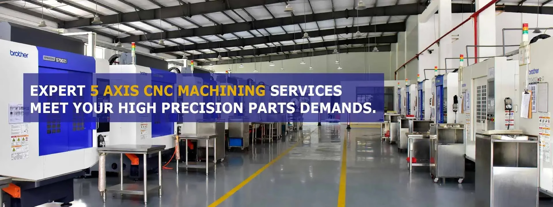
CNC processing covers milling, turning and mill-turn work on one shop floor. GreatLight runs 127 high-precision machines across three wholly-owned plants, including 16 simultaneous 5-axis machining centers. The rest of this page explains the mechanics, the limits, and how to pick the right machine for a given part.
From CAD model to G-code: the chain of steps
The chain starts with a solid model. A designer builds it in CAD, usually as a step or parasolid file, with tolerances and datum callouts already decided. Mark the critical features before the model leaves the design office. A hole pattern that needs ±0.010 mm location should say so on the drawing, because the CAM programmer will set up for the tightest callout on the part.
CAM software converts the solid into toolpaths. The programmer chooses tool diameter, stepover, stepdown, feed per tooth and spindle speed, then posts the result as G-code. Typical G-code contains rapid moves (G00), linear feeds (G01), arcs (G02/G03), tool length compensation, and work coordinate offsets. A post-processor translates generic CAM output into the dialect the machine control expects.
Setup is where the plan meets the metal. The operator mounts the stock in a vise, chuck or fixture, probes the datum, loads tools into the carousel, and touches off each tool length. On a 5-axis machine, the rotary table needs its own alignment. A 0.02 mm error in rotary center shows up as a taper on a long cut, so probing routines matter more than most people expect.
Then the program runs. The first article comes off the machine and goes to inspection. If it passes, production continues with in-process checks. If it fails, the programmer adjusts offsets or toolpaths and cuts again. This loop is short, usually hours, which is why machining suits prototypes and bridge production as well as repeat runs.
What happens where the tool meets the workpiece
Cutting is controlled fracture. The tool edge presses into the material until shear stress exceeds the material strength, and a chip separates. Heat is generated in three places: the shear zone, the chip-tool interface, and the flank rubbing against the finished surface. Most of it leaves with the chip, which is why chip evacuation is a machining concern and not a housekeeping one.
Speeds and feeds follow from this. Aluminum 6061 cuts at 300–600 m/min surface speed with carbide, while 316 stainless runs at 80–150 m/min. Titanium Ti-6Al-4V is slower still, around 30–60 m/min, because it conducts heat poorly and work-hardens at the cut. Push too hard and the edge chips; too light and the tool rubs instead of cutting, which dulls it faster than a heavy cut.
Tool geometry sets the surface finish. A finishing end mill with a 0.8 mm corner radius leaves a different floor than a sharp corner tool, and a wiper insert on a lathe can reach Ra 0.8–1.6 μm in one pass on steel. As-machined surfaces usually land at Ra 1.6–3.2 μm. If the print calls for Ra 0.2–0.8 μm, plan on a separate finishing pass or a secondary operation.
Chatter is the common failure mode. Long tools, thin walls and weak fixturing let the tool and workpiece resonate. The fix is usually a shorter tool, more support, or a change in spindle speed. A part with a 0.5 mm wall and a 40 mm depth is a chatter case waiting to happen, and no feed table will save it.
Tolerances, finishes and where they break down
±0.005 mm is achievable, but it is a per-feature commitment, not a blanket number for the whole part. A bore can hold that. A 300 mm long slot usually cannot, because thermal expansion and machine geometry stack up over distance. Aluminum grows about 0.023 mm per meter per degree Celsius, so a 5 °C shop swing moves a long feature more than the tolerance allows.
Datums decide whether the tolerance means anything. If a hole pattern is dimensioned from a face that gets machined in a second setup, the stack-up includes the re-fixturing error. Put the critical datums on the first setup whenever the design allows it, and inspect from the same datums the drawing uses.
Surface finish and tolerance trade against each other. Polishing a surface to Ra 0.2 μm can move the geometry by a few micrometers, which eats into a ±0.005 mm callout. Call out finish only where it matters: sealing faces, sliding surfaces, optical bores. A cosmetic panel does not need the same finish as a hydraulic spool bore.
Thin walls, deep pockets and sharp internal corners each have a physical floor. A 1 mm end mill can reach a 1 mm internal radius but only about 5 mm deep before deflection ruins the cut. Deep pockets need either a larger radius or EDM. These are geometry limits, not machine limits, and they apply in every shop.
Material choice changes the whole setup
Aluminum is the default for prototypes and most enclosures. 6061-T6 machines cleanly, takes anodizing well, and holds tight tolerances without much fuss. 7075 is stronger but gummier at the cut and costs more. Cast aluminum ADC12 behaves differently again because porosity can open up under a finishing pass.
Stainless separates the easy grades from the difficult ones. 303 is free-machining and predictable. 304 and 316 work-harden, so the tool has to stay engaged and the feed must not dwell. 17-4PH machines reasonably in the annealed condition and then goes to heat treat, which moves dimensions; leave stock for a post-heat-treat finishing pass if the print is tight.
Titanium, Inconel and magnesium each carry their own rules. Ti-6Al-4V needs sharp edges, low surface speed and plenty of coolant. Inconel destroys tools quickly and often justifies a rough-then-wire-EDM route. Magnesium AZ31B and AZ91D cut fast but require chip control because fine magnesium swarf is a fire risk.
Plastics are not softer versions of metal. POM and PEEK hold good tolerances but move with temperature. ABS and PC can melt at the cut if the feed is too slow. Carbon fibre wears carbide edges fast, so plan on more tool changes than the same part in aluminum. The material datasheet plus a quick DFM review settles most of this before the first chip.
Where CNC processing fits in a product program
CNC processing is the bridge between a design and a production process. It is fast enough for 10 to 100 units, accurate enough to validate a design, and flexible enough to absorb engineering changes between runs. A change in wall thickness or hole location costs a CAM edit, not a new mold.
Use it as a validation step before tooling. Machined parts match the final geometry closely enough to run functional tests, fit checks and regulatory samples. If the design changes after those tests, only the program changes. That is cheaper than cutting a second mold.
Use it as production when volumes are modest. With no minimum order quantity, a run can start at one prototype and scale to 10,000+ parts without a tooling investment. Production can start within 24 hours of an approved quote, and parts typically ship in 3–5 days.
It is also the fallback when another process cannot hold a feature. Die casting cannot hit a sharp internal corner. Injection molding cannot deliver a 20 mm thick solid section without sink. In both cases, machining a few critical features after the primary process is often the cheapest path to a print-compliant part.
Which machine type fits your part
Pick by geometry, tolerance and quantity, not by machine prestige.
| Machine type | Best for | Watch out for |
|---|---|---|
| 3-axis mill | Flat plates, pockets, open faces, one setup per side | Each face needs its own setup and re-datum |
| 4-axis mill | Shafts, cylinders, hole patterns around a diameter | Only one rotary axis, so undercuts limit reach |
| 5-axis simultaneous | Curved surfaces, impellers, complex contours in one setup | Higher hourly rate; needs good CAM support |
| Mill-turn | Parts with both turned and milled features | Not ideal for very long shafts |
| Lathe | Round parts, threads, bores, high volume turning | Off-axis holes need a second operation |
| EDM | Sharp internal corners, hardened tool steel | Slow; not for bulk material removal |
The short answer on machine selection
If your part has curved surfaces or needs several faces machined in one setup, choose 5-axis. If it is flat, prismatic, or round, a 3-axis mill or a lathe will usually hold the tolerance at a lower hourly rate.
Common questions about CNC processing
How tight a tolerance can CNC processing hold in production?
±0.005 mm is realistic on critical features with the right machine, fixturing and temperature control. It is not realistic as a blanket callout across a 500 mm part.
Call out the tight tolerance only on the features that need it. Everything else can sit at a general tolerance, which keeps the cycle time and the cost down.
What file format do you need for a quote?
A step or parasolid solid model plus a 2D drawing with tolerances and datums. The drawing carries information the solid cannot, like which surface is the datum and which features are critical.
A PDF drawing alone can be quoted, but it slows the DFM review because the geometry has to be rebuilt before toolpaths can be planned.
Can CNC processing replace injection molding for production?
For low and mid volumes, yes. With no minimum order quantity, machining can run from one prototype to 10,000+ parts.
Above that, molding usually wins on unit cost. The crossover depends on part size, geometry and material, not on a fixed number.
How does the shop protect design data?
Uploads are handled as confidential, and a non-disclosure agreement is available on request. ISO 27001:2022 covers information security management at the company level.
If your program requires it, sign the NDA before sending models and drawings.
What surface finishes are available after machining?
Anodizing, electroless nickel, zinc, silver and gold plating, powder coating, black oxide, bead blasting, tumbling, brushing and polishing. Laser marking is available down to 1.5 mm character height.
Finish choice often drives the tolerance plan, so decide it before the finishing passes are programmed.
How fast can a CNC order start?
Quotation and a free DFM analysis come back within 12 hours. Production can start within 24 hours of approval, and parts typically ship in 3–5 days.
Rush schedules depend on material availability and machine capacity at the time of the order.
Send a model, get a quote and a DFM review
Upload your step file and drawing. We return a quotation and a free DFM analysis within 12 hours, with no minimum order quantity.
12-hour quote100% inspectionNDA on request
More from the shop floor
We publish setup notes, tooling trials and inspection data from the factory floor.











