
Design Driven OEM Metal Die Casting ODM
This page explains how a design driven OEM metal die casting ODM program works in practice, from the first DFM pass to the last inspection. It is written for design engineers and sourcing teams who must decide whether a part should be cast, how it should be gated, and where the real tolerance limits sit.
In this article
- 1
- 2
- 3
- 4
- 5
- 6
- 7
What OEM Metal Die Casting ODM Actually Means
OEM means you bring a finished drawing and a supplier builds it. ODM means the supplier helps create the design as well. A design driven OEM metal die casting ODM program sits in the middle: the supplier takes your functional requirement, proposes geometry and process changes, then casts and machines the part under one roof.
The reason this matters is thermal. Molten aluminium enters a die at roughly 650–700 °C and solidifies in under a second on thin walls. Shrinkage, gate placement, and die temperature decide where porosity lands before anyone cuts steel. If the drawing is frozen before those variables are modeled, the foundry can only react. The designer has already given away the cheapest place to fix the problem.
So the useful question is not OEM or ODM. It is who owns the feedback loop between the CAD model, the simulation, and the tool shop. When one team owns all three, a wall thickness change on Tuesday shows up as a revised gate on Thursday, not as a scrapped tool three months later.
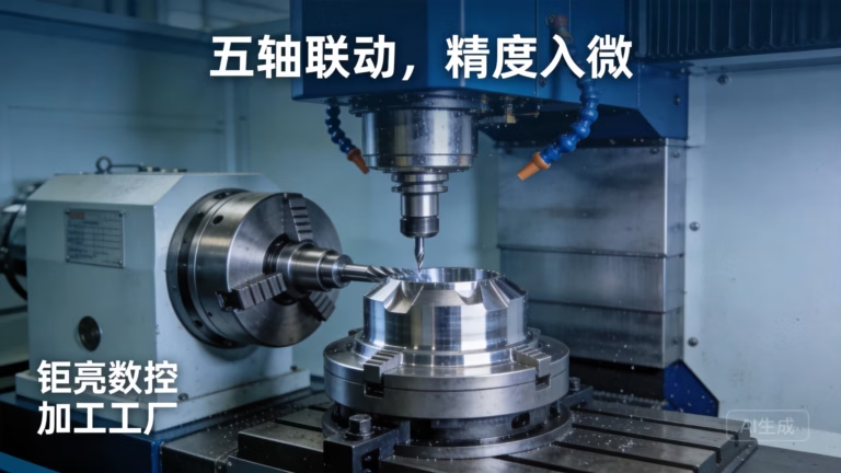
GreatLight runs this loop with 127 high-precision CNC machines across 3 wholly-owned plants, plus die casting and finishing in the same group. A part can be cast, stress-relieved, machined on a 5-axis center, and inspected without leaving the supply chain. That is the practical definition of design driven.
- 1OEM inputA released drawing, tolerances and material callout
- 2ODM inputA function, envelope, load case and annual volume
- 3Design driven outputA castable, machinable, inspectable part definition
Design for Manufacturability at the Core
DFM is not a checklist run after the design is done. In die casting it is a set of physical limits that decide whether a feature can be filled at all. Wall thickness is the first limit. For aluminium, 2.0–4.0 mm covers most structural housings; below 1.5 mm the metal freezes before it reaches the end of the flow path, and above 6 mm you invite shrinkage voids in the thick section.
Draft is second. A 1–2° draft on inside walls and 1.5–3° on outside walls lets the part release without galling. Text and ribs need more, often 3–5°, because they sit in pockets where the die grips hardest. Sharp internal corners are the third limit: a fillet of at least half the wall thickness spreads stress and keeps the die from cracking at the corner.
Then come the features that cannot be cast cleanly. Cross holes, fine threads, and sealing faces usually get stock left on them and are finished by CNC. That is a deliberate cost decision, not a defect. Casting the rough shape and machining only the critical 5–10% of surfaces is almost always cheaper than casting to net shape and rejecting parts.
A free DFM analysis within 12 hours is the practical entry point. The output should name the specific features at risk, the wall thickness changes proposed, and the datum scheme that will be used for inspection. A report that only says "part is castable" is not a DFM report.
- 1Wall thickness2.0–4.0 mm for aluminium structural parts
- 2Draft angle1–2° inside, 1.5–3° outside; 3–5° on ribs and text
- 3Corner filletsAt least half the local wall thickness
- 4Machined stock0.3–0.8 mm on faces held to ±0.005 mm
How Gating and Thermal Control Set Final Quality
A die casting die is a heat exchanger as much as a mold. Half the heat leaves through the die steel, half leaves with the part. If the die runs cold, the metal freezes early and you get cold shuts and incomplete fills. If it runs hot, cycle time climbs and shrinkage porosity moves into the thick sections.
Gates decide the fill pattern. A single gate feeding a long part pushes metal down one path and leaves a cold front at the far end. Multiple gates balance the fill but create weld lines where the fronts meet. Those weld lines are weak points, and they must not land on a sealing face or a fatigue-critical boss. Simulation moves them to low-stress areas before the die is cut.
Overflows and vents are the third control. Trapped air has to leave the cavity before the metal seals it off. Poor venting shows up as surface blisters and subsurface gas porosity that only appears after machining. Parts that will be machined on a critical face need more venting than the drawing suggests.
Vacuum-assisted casting reduces gas porosity further and is worth the cycle-time cost on pressure-tight parts such as pump housings and EV battery enclosures. On a simple bracket, it adds cost with no benefit. Match the process to the leak requirement, not to the marketing.
Where Die Casting Tolerances Stop and Machining Starts
As-cast tolerances follow the alloy and the dimension. A general as-cast band on aluminium is roughly ±0.1 mm on small dimensions, widening with part length because the die and the part expand differently as they cool. That is a different world from the ±0.005 mm that a CNC machine holds on a machined face.
This gap is the single most common source of arguments between design and production. A drawing that puts ±0.02 mm on an as-cast boss is asking for a capability the process does not have. The fix is to add stock and machine it. A 0.5 mm stock allowance turns an impossible cast tolerance into a routine turning or milling operation.
Datum selection decides whether inspection is meaningful. Cast datums are rough surfaces, so using them directly produces scatter that looks like process variation. Machining a small datum pad first, then referencing all other measurements to it, removes that noise. This is why a design driven program defines the datum scheme at the same time as the part geometry.
Material choice closes the loop. ADC12 fills thin walls well and is the default for complex housings. 6061 and 7075 are not die casting alloys; when a drawing calls for them, the part is usually better machined from billet or cast in a suitable alloy and then machined. Getting that call right early saves an entire tooling cycle.
- 1As-cast±0.1 mm typical, widening with part length
- 2Machined±0.005 mm on referenced faces and bores
- 3Surface finishRa 0.8–1.6 μm machined; Ra 0.2–0.8 μm on fine bores
- 4Stock allowance0.3–0.8 mm on faces to be machined
Full Process Chain Integration and Its Limits
Integration means the casting, the heat treat, the machining, and the finish are planned as one sequence. A part that is quenched or stress-relieved between casting and machining will move. If the machining program assumes a stable casting, the first article passes and production drifts. Planning the sequence is what prevents that.
The same logic applies to finishing. Anodizing removes a few micrometres and can change a press-fit bore. Powder coating adds 60–120 μm and can close a thread. Deciding the finish before the machining drawing is released keeps those allowances in the right place.
Integration has limits. Very large parts, exotic alloys, and low volumes often do not justify a die. A 4,000 mm maximum processing size covers most housings, but a one-off bracket is cheaper as a machined or fabricated part. A design driven supplier should say so rather than sell a tool.
Volume is the other limit. Die casting pays back on runs where tooling cost is spread across thousands of parts. From one prototype to 10,000+ part runs, the economics shift. Below a few hundred pieces, machining from billet or vacuum casting usually wins on total cost.
Quality Assurance for Cast and Machined Features
Casting defects are not all visible. Surface porosity shows as pinholes; internal porosity hides until a part is machined or pressure-tested. A serious inspection plan separates the two and tests each with the right method. Visual checks catch surface issues. X-ray or sectioning catches the internal ones on critical parts.
A practical plan covers three stages. Raw material is verified against the alloy certificate before melting. In-process checks monitor die temperature, fill time, and shot weight, since a drifting shot weight is the earliest sign of a gate wearing. Final inspection measures the drawing dimensions on the datum scheme defined during DFM.
For safety-related parts, IATF 16949 and ISO 13485 frameworks require traceability from the heat number to the finished part. That means the casting, the machining batch, and the finish lot are all linked. It also means a change in alloy supplier triggers a re-qualification, not a silent substitution.
100% inspection before shipment, with reports on request, is the baseline. What matters more is the measurement capability behind it. A ±0.005 mm callout is meaningless if the gauge cannot resolve 0.001 mm. Ask which instrument will be used on each critical dimension before the first article is made.
- 1IncomingAlloy certificate and melt verification
- 2In-processDie temperature, fill time, shot weight trending
- 3FinalDimensional report against the DFM datum scheme
OEM Drawing Supply vs Design Driven ODM
Use this to decide which engagement model fits a given part.
| Factor | OEM drawing supply | Design driven ODM |
|---|---|---|
| Design ownership | Customer owns all geometry | Shared; supplier proposes changes |
| Best for | Stable, proven part design | New part or unresolved defects |
| DFM timing | After quote, often optional | Before tooling, built into quote |
| Typical wall issues | Found at first article | Resolved in simulation |
| Datum scheme | Customer-defined | Defined jointly for inspection |
| Change cost | High after tooling | Lower, caught pre-tooling |
| Volume fit | Any volume | Best above a few hundred parts |
| Lead time driver | Tooling only | DFM plus tooling plus machining |
When to Choose Which Model
If the design is frozen and the part already casts well, use OEM drawing supply and compete on price and lead time. If the part is new, fails pressure testing, or carries tight machined features next to as-cast surfaces, use a design driven OEM metal die casting ODM partner and pay for the DFM pass before any steel is cut.
Common Questions
Can a die casting be held to ±0.005 mm without machining?
No. As-cast tolerances are roughly ±0.1 mm on small aluminium dimensions and widen with part length. The ±0.005 mm figure applies to machined features referenced to a defined datum.
The usual approach is to leave 0.3–0.8 mm of stock on critical faces and bores, then machine them after the casting has stabilized.
Why does my part show porosity only after machining?
Subsurface gas or shrinkage porosity sits just below the skin. The skin is dense because it froze against the die wall; the interior cooled slower and trapped gas or shrank away.
Machining removes the skin and exposes it. More venting, vacuum assistance, or moving the gate away from that area are the standard remedies.
What wall thickness should I use for an aluminium housing?
For structural aluminium housings, 2.0–4.0 mm covers most cases. Ribs can go thinner, down to about 1.5 mm, if they are short and well vented.
Above 6 mm, shrinkage voids become likely in the thick section. If a design needs a thick boss, core it out or accept a machined pocket.
Is a die casting tool worth it for a low volume run?
Usually not below a few hundred parts. The tooling cost has to be spread across the run, and at low volume the per-part cost stays high.
For prototypes and small batches, machining from billet or vacuum casting gives comparable geometry without a die. The switch point depends on part size and complexity.
Who owns the design in an ODM program?
It varies by contract. In most design driven programs the customer owns the part geometry and the supplier owns the process and tooling design.
Confirm this in writing before quoting. Uploads are kept secure and confidential, and an NDA is available on request.
How does finishing affect cast tolerances?
Anodizing removes a few micrometres and barely moves a dimension. Powder coating adds 60–120 μm per side and can close a thread or a press fit.
Decide the finish before the machining drawing is released so the allowance lands in the right place.
Send the Function, Not Just the Drawing
Share the part envelope, load case, and annual volume. We return a quotation and a free DFM analysis within 12 hours, with the specific features we would change and why.
12-hour quoteFree DFM analysis100% inspectionNo MOQ
More from GreatLight
We publish setup notes, tooling trials and inspection data from the factory floor.











