
Gyroscope Housings Die Casting for Electric Car IMU Modules
The gyroscope housing holds MEMS sensors that feed ADAS, stability control and suspension logic. This page explains how gyroscope housings die casting actually behaves in production: where the process wins, where it fails, and which features must be machined afterward.
What an IMU Housing Has to Do
An inertial measurement unit combines gyroscopes and accelerometers on a small PCB. The housing does four jobs at once: it locates that PCB repeatably, shields it from electromagnetic noise, pulls heat away from the sensor die, and survives the vibration and thermal load of a vehicle for its full service life.
Those jobs pull in different directions. Shielding wants a continuous conductive wall. Locating wants stiffness and flatness. Heat rejection wants thin sections and good thermal paths. Mass reduction wants less metal everywhere. Gyroscope housings die casting lets us trade these against each other in one part, because wall thickness and rib layout are set by the die rather than by a stack of operations.
The performance number that matters most is not the housing itself. It is the signal-to-noise ratio at the sensor. If the housing flexes, the PCB moves. A few micrometers of movement shows up as bias drift, and drift is what an ADAS algorithm cannot filter out.
- 1LocateBores and pads position the PCB within the sensor's alignment budget.
- 2ShieldA grounded conductive enclosure reduces EMI reaching the sensor traces.
- 3Reject heatMetal walls give a low-resistance path away from the die.
- 4SurviveRibs and bosses carry road vibration without fatigue cracking.
Why Aluminum HPDC Fits This Part
High-pressure die casting injects molten aluminum into a steel die at high velocity and solidifies it under pressure. For a housing with mounting bosses, connector cutouts, cooling ribs and a sensor pocket, that single shot replaces several milling setups. ADC12 and similar Al-Si alloys flow well into thin walls and hold the near-net shape well enough that machining becomes a finishing step, not a shaping step.
General as-cast features land around ±0.1 mm. That is fine for outer profiles, ribs and non-critical bosses. It is not fine for a bearing bore or a sensor seating face, and no die caster should tell you otherwise. Those surfaces get machined after casting, and the casting's job is to leave enough, but not too much, stock for that operation.
Volume decides the economics. A die has a fixed cost that has to be spread across parts. Low-volume or prototype programs are usually better served by CNC machining from billet or by vacuum casting, both of which skip tooling. Once annual volume is steady and the geometry is frozen, gyroscope housings die casting becomes the cheaper route per part.
The design must respect draft and wall uniformity. Sharp internal corners concentrate stress and cause shrinkage porosity. A 1.5–2° draft on side walls, generous fillets, and wall thickness held in a narrow band around 2–3 mm all reduce scrap before the first shot is ever made.
- 1Right fitMedium to high annual volume, frozen geometry, complex ribbed shape.
- 2Wrong fitUnder a few thousand parts per year, or a shape still changing weekly.
- 3WatchDraft angle, fillet radius and wall uniformity drive yield more than alloy choice.
Porosity, Pressure Tightness and Thermal Creep
Gas porosity is the defect that ends programs. Turbulent fill traps air, and the trapped air becomes a void just under the skin. If that void sits on a sealing face or a threaded boss, the part leaks or the thread strips. Vacuum-assisted shot profiles and carefully placed overflows move gas out of the cavity before it can be entrained.
Pressure tightness is a separate requirement from strength. A housing can pass a tensile check and still weep through a micro-void network. Helium leak testing on sealed cavities is the honest test; dye penetrant only finds surface-breaking defects. Where a sealed enclosure is required, specify the leak rate and the test method on the drawing.
Thermal cycling is the slow failure. The housing expands with temperature, the steel fasteners expand less, and the joint preload changes with every cycle. If the casting creeps, the PCB reference plane drifts and the sensor bias shifts with it. Aluminum holds its shape well, but only if the casting is properly densified and the assembly stack is designed for the differential.
Wall thickness matters here too. Thin walls heat and cool fast; thick bosses lag behind. That mismatch builds internal stress into the part, and the part relieves that stress over thousands of thermal cycles. Uniform walls, or a thermal soak before final machining, remove most of it.
- 1Gas porosityTrapped air from turbulent fill; shows on sealing faces and threads.
- 2Shrinkage porosityHeavy sections feeding thin ones; worst at thick-to-thin junctions.
- 3Cold shutTwo flow fronts meeting below fusion temperature; weak, non-visible seam.
What Has to Be Machined After the Casting
The casting arrives with maybe 0.3–0.6 mm of stock on the surfaces that matter. Those surfaces are usually the sensor seating face, the connector opening, the mounting bores and any thread. Everything else stays as-cast.
Flatness on the sensor pad is the one to watch. A pad that is flat to 0.02 mm lets the PCB sit without shimming and keeps the gyroscope axes aligned to the vehicle frame. A pad that is warped by 0.1 mm forces a soft gasket, and a soft gasket adds a compliance path that shows up as vibration sensitivity.
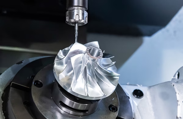
Bores and threads come next. A Ø8 H7 bore with a perpendicularity callout needs a single setup to hold the relationship between the bore axis and the seating face. Move the part between setups and the stack-up eats the tolerance. Five-axis machining with a Ø400 mm rotary table lets us reach the side features without re-fixturing.
Finishes follow. Anodizing or a conductive coating on the inside walls carries the shielding function; a hardcoat on the outside handles wear. Laser marking needs at least 1.5 mm character height to stay legible after coating. Bead blasting before coating improves adhesion but can round a sharp edge, so mask any edge that defines a sealing line.
- 1Face flatnessTarget 0.02 mm on the sensor pad; check after coating, not before.
- 2Bore alignmentCut the bore and its datum face in one setup to protect perpendicularity.
- 3Thread depthCast bosses need enough wall to hold full thread engagement.
How to Tell a Housing Is Actually Good
A dimensional report on the machined features is necessary but not sufficient. It tells you the part matches the drawing. It does not tell you the casting is dense, the coating is continuous, or the assembly keeps its alignment after a thermal soak.
Ask for the process data behind the parts. Shot profiles, die temperature logs and X-ray or CT scans on first articles show whether the process is in control or whether the good parts were luck. A supplier who cannot show that data is asking you to accept a promise.
Then test the assembly, not just the part. Bolt the housing to a representative mass, run a thermal cycle from -40 °C to +85 °C, and measure the sensor bias before and after. That single test catches porosity-driven creep, coating breakdown and preload loss in one pass.
Incoming inspection should check the features the sensor depends on, not every dimension on the print. Flatness, bore position and thread condition each have a direct path to signal quality. Cosmetic surfaces do not.
- 1First articleCT or X-ray plus full dimensional report on the machined features.
- 2Process dataShot profile and die temperature records, not just a pass stamp.
- 3Assembly testThermal cycle and bias measurement on the bolted assembly.
Which Process Route Fits Your Housing Program
Match the route to volume, geometry maturity and tolerance demand.
| Route | Typical Volume | As-Built Tolerance | When It Makes Sense |
|---|---|---|---|
| Aluminum HPDC | Medium to high | ±0.1 mm as-cast | Frozen ribbed geometry, tooling cost amortized |
| Vacuum casting | Low to medium | ±0.2 mm typical | Bridge tooling, small series, design still moving |
| CNC from billet | One to thousands | ±0.005 mm | Prototypes, low volume, tight bores without tooling |
| HPDC + 5-axis CNC | Medium to high | ±0.005 mm on machined faces | Sealing faces, bearing bores, sensor pads |
| HPDC + vacuum assist | Medium to high | ±0.1 mm as-cast | Sealed enclosures with a specified leak rate |
The Honest Trade-Off
If your volume is steady and the geometry is frozen, cast the housing and machine only the critical faces. If the design is still moving or the annual volume is low, machine from billet and skip the tooling investment until the shape settles.
Common Questions
Can die casting hold the tolerance on a gyroscope bore?
Not as-cast. General die-cast features land around ±0.1 mm. A bore that positions a sensor or a bearing is machined afterward, and that operation can hold ±0.005 mm on a CNC.
The casting's role is to leave consistent stock and a stable datum, so the machining operation is repeatable from part to part.
Which aluminum alloy should the housing use?
ADC12 and similar Al-Si die-casting alloys are the usual choice because they flow into thin ribs and hold near-net shape well.
If the housing also needs structural stiffness or a specific thermal path, we review the alloy against the wall sections before tooling is cut. Changing alloy after the die exists is expensive.
How is porosity detected before the parts ship?
X-ray or CT scanning on first articles shows internal voids. For sealed enclosures we also rely on a leak test at a specified rate.
Dye penetrant only finds defects that reach the surface, so it is not a substitute for either method on a pressure-tight part.
What post-casting finishes work on these housings?
Anodizing in clear, color, hardcoat or conductive versions is common. Electroless nickel and zinc plating are options when a conductive or corrosion-resistant surface is needed.
Bead blasting and tumbling improve appearance and coating adhesion. Laser marking needs at least 1.5 mm character height to stay readable after coating.
What is the smallest order you will run?
There is no minimum order quantity. We run from a single prototype to 10,000+ piece production runs.
For a prototype, machining from billet is usually faster than cutting a die, and it lets the design change without retooling.
Do you sign an NDA before we share drawings?
Yes. Uploads are kept secure and confidential, and an NDA is available on request before any file changes hands.
We can also review a drawing and return a DFM analysis within 12 hours so you know where the casting will need machining.
Send the Drawing, Get a DFM Review
Upload a STEP file and a housing drawing. We will tell you which features can stay as-cast, which need machining, and where the wall sections will fight you.
12-hour quoteDFM analysis100% inspection
More From GreatLight
We publish setup notes, tooling trials and inspection data from the factory floor.











