
Global Custom 3 Axis CNC Machining Exporters: How the Process Actually Works
A plain walkthrough of what three-axis machining can and cannot hold, how an export order moves from drawing to crate, and which checks tell you whether a supplier is set up for your part. Written for design and sourcing engineers comparing global custom 3 axis cnc machining exporters.
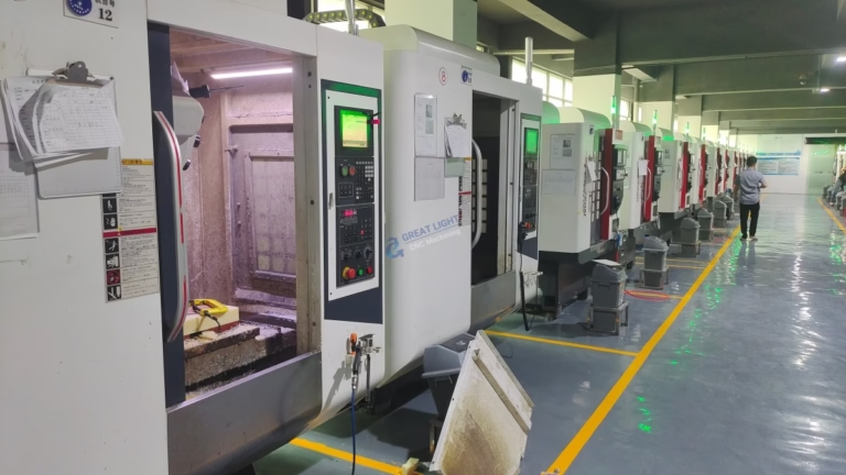
What 3 Axis Machining Physically Does
A three-axis machining center moves the cutting tool along three linear axes: X left and right, Y forward and back, Z up and down. The worktable stays still. No rotary table, no tilting spindle. The tool always approaches the part from one direction at a time.
That single constraint explains almost everything about the process. Because the tool axis never tilts, every machined face must be reachable from above, or from the side if the part is re-fixtured. Undercuts, deep side pockets and features on the back of a part cannot be cut in one setup.
The upside is predictability. Fewer axes means fewer stacked error sources. There is no rotary table indexing error, no spindle tilt compensation to verify, and no collision envelope to model in the CAM file. A three-axis program is short and easy to audit.
The trade-off is setup count. A part with features on five faces becomes five operations, each with its own fixture, its own datum shift and its own chance of a locating error. That is where a three-axis quote gets expensive, not in the cutting time.
- 1One tool direction per setupReachability drives the whole process plan.
- 2Short, auditable programsFewer error sources to verify before first cut.
- 3Setup count is the real cost driverFive faces means five fixtures, not five axes.
- 4Prismatic parts fit bestPlates, brackets, housings, manifolds, heat sinks.
Which Parts Belong on Three Axes
Three-axis work suits parts whose features open toward one or two directions. Flat plates with drilled hole patterns, machined housings with a single open cavity, heat sinks with straight fins, and manifolds with ports on one face all cut cleanly on three axes.
A useful test: draw a line through every feature normal to its machined surface. If most of those lines point the same way, the part is a three-axis part. If they fan out in five directions, it is not, and forcing it into three-axis tooling adds fixtures rather than removing cost.
Some parts sit on the boundary. A housing with a deep cavity plus four side ports can be done on three axes if the ports are shallow enough to drill from a second setup on a tombstone. Once the ports need a contoured blend into the cavity wall, the extra setups usually cost more than the five-axis rate.
Size matters too. Three-axis beds in a mixed shop typically run from 500 × 500 × 450 mm up to 750 × 1,150 × 550 mm, with long-bed machines reaching 4,000 × 400 × 150 mm for extrusion rails, structural beams and long brackets.
Parts over about 1,200 mm in two directions usually need a long-bed three-axis machine rather than a five-axis center, because the five-axis envelope rarely stretches that far. That is a real reason to keep three-axis capacity in a supply chain.
- 1Good fitPlates, brackets, single-cavity housings, heat sinks, manifolds.
- 2Poor fitImpellers, turbine blades, deep undercuts, blended 3D contours.
- 3BorderlineShallow side ports add setups; deep blended ports add error.
- 4Long parts4,000 mm travel suits rails and beams.
Where the Tolerance Actually Goes
A shop advertising ±0.005 mm on a three-axis machine is describing what the machine holds under controlled conditions: temperature-stable room, light finishing passes, sharp tooling, verified thermal drift. It is not a blanket promise on every dimension of every part.
On a real part, errors stack. Fixture locating error, tool wear, spindle thermal growth, material stress release and the metrology method all add in. A part with ±0.02 mm on bolt holes and ±0.05 mm on the outer profile is a normal, well-behaved three-axis part.
Tight callouts belong on the features that need them. Dowel holes, bearing bores and mating spigots deserve the tight tolerance. Cosmetic edges, clearance slots and weight-relief pockets do not. Sending a drawing where everything is ±0.01 mm raises inspection time and often the price, without improving function.
Surface finish follows the same logic. As-machined finish lands around Ra 1.6–3.2 μm. A high-quality finish of Ra 0.8–1.6 μm needs a finishing pass with a fresh tool and slower feed. Fine finishes of Ra 0.2–0.8 μm demand more passes and more inspection, so reserve them for sealing faces and bearing seats.
For reference, ±0.005 mm equals ±0.0002 in. If your drawing is in inches, state the unit clearly. Unit confusion on a bore diameter is one of the most common causes of a scrapped first article.
- 1Tight where it functionsBores, dowels, spigots, sealing faces.
- 2Loose where it does notClearance holes, weight relief, cosmetic edges.
- 3Finish costs follow the same ruleRa 0.2–0.8 μm only where a seal or bearing needs it.
- 4State the unit±0.005 mm is ±0.0002 in. Mixed units scrap parts.
How an Export Order Moves Through the Shop
An export order from a global supplier follows the same path as a domestic one, with two additions: documentation and packing. The technical work is not different. What changes is the paperwork that has to travel with the parts.
It starts with a drawing review. A useful supplier returns a DFM note within 12 hours alongside the quote, flagging thin walls, unreachable features, ambiguous datums and tolerances that cannot be measured with standard gauges. Those notes save a revision cycle.
Then programming and first-article machining. On a clean job, production can start within 24 hours of drawing release. The first article gets measured against the drawing, not against the CAD model, because the drawing is the contract.
After that, production runs, in-process checks happen at set intervals, and every part gets a final inspection before packing. Parts typically ship in 3–5 days. Material certificates, dimensional reports and finish certificates travel with the shipment when the purchase order asks for them.
Packing is not a detail. Machined faces dent each other in transit. Parts should be individually wrapped, separated by dividers, and shipped with desiccant if the route crosses humid climates. A supplier that packs loose parts in one box is telling you something about the rest of the process.
- 1DFM feedback firstFlags unreachable features before you cut metal.
- 2First article measured to drawingCAD is a model; the drawing is the contract.
- 3Reports on requestMaterial, dimensional and finish certificates.
- 4Packing protects the finishIndividually wrapped, divided, desiccated.
Five Checks on a Three-Axis Supplier
Score each row against your part and your purchase order.
| Check | What to Ask | Good Answer | Red Flag |
|---|---|---|---|
| Machine travel | What is the bed size and Z clearance? | Quoted travel covers your part plus fixture | Quotes before asking part dimensions |
| Tolerance method | How do you verify a ±0.02 mm bore? | Names the gauge, CMM or bore mic used | Says the machine holds it, no method |
| Setup plan | How many setups does my part need? | Gives a number and the datum for each | One setup, no detail |
| Documentation | Can you send material and dimensional reports? | Yes, on request with the shipment | No reports, or costs extra per part |
| Packing | How are finished faces protected? | Individual wrap, dividers, desiccant | Loose parts in a single carton |
| Capacity fit | Is this part on a 3-axis or 5-axis machine? | Explains why one is cheaper for this part | Every part goes on the same machine |
| Change handling | What happens if a drawing revises mid-run? | Written change note with cost and date | Verbal only, price moves later |
Material Choices and What They Do to the Cut
Same geometry, different chip behavior and different finishing route.
| Material Group | Typical Grades | Machining Note | Common Use |
|---|---|---|---|
| Aluminum | 6061-T6, 7075, 6082, ADC12 | Fast, low tool wear, good finish off the tool | Brackets, housings, heat sinks |
| Stainless | 303, 304, 316L, 17-4PH | 303 cuts free; 316L work-hardens if fed too slow | Medical, food, marine parts |
| Carbon steel | 1018, 1045, 4140, 4340 | 1045 and 4140 need carbide and steady feed | Shafts, plates, structural parts |
| Titanium | TA2, TC4 (Ti-6Al-4V) | Low speed, high coolant, sharp tools, no dwell | Aerospace, medical implants |
| Copper alloys | C110, C36000, beryllium copper | Gummy; sharp edges and high rake angles help | Busbars, RF cavities, connectors |
| Plastics | POM, PEEK, PC, PMMA | Climb cut, air blast, watch thermal growth | Insulators, jigs, prototypes |
The Verdict: Match the Axes to the Geometry, Not the Price List
If your part is prismatic with features opening in one or two directions, three-axis machining is the cheaper and more repeatable route, and global custom 3 axis cnc machining exporters with long-bed capacity cover the large flat parts five-axis shops cannot reach. If the part has blended 3D contours, deep undercuts or five-face features in one setup, go to five-axis and accept the rate. Do not pay five-axis prices for a plate, and do not pay for five fixtures to avoid a rotary table.
Questions Engineers Ask Before Ordering
Can three-axis machining hold ±0.005 mm?
Yes, on specific features under controlled conditions: temperature-stable room, light finishing passes, sharp tooling and a clean fixture. The tolerance applies to the dimensions you call out, not to the whole part.
In practice, most three-axis parts run comfortably between ±0.02 mm and ±0.05 mm on general dimensions, with the tight callouts reserved for bores, dowel holes and mating faces.
How do I know if my part needs a fourth axis?
Count the faces that carry machined features. If two or more faces need work and the part is small enough to rotate on a table, a fourth axis saves setups and improves positional accuracy between faces.
If all machined faces open the same way, a fourth axis adds cost with no accuracy gain. Keep it on three axes and spend the money on a better fixture.
What is the largest part a three-axis machine can handle?
On long-bed machines, travel can reach 4,000 × 400 × 150 mm. Standard vertical beds commonly cover 750 × 1,150 × 550 mm or 600 × 600 × 600 mm, and compact beds 500 × 500 × 450 mm.
The limiting factor is usually Z clearance once the fixture and tool holder are loaded, not the X and Y travel printed in the brochure.
Which surface finishes are realistic on three axes?
As-machined finish lands around Ra 1.6–3.2 μm. A high-quality finish of Ra 0.8–1.6 μm is achievable with a dedicated finishing pass.
Finishes of Ra 0.2–0.8 μm are possible but need more passes, fresh tooling and more inspection, so specify them only for sealing faces and bearing seats.
Should I send the CAD model or the drawing?
Send both, and make clear which one governs. The first article is measured against the drawing, because that is the document carrying tolerances and datums.
If the CAD model and the drawing disagree on a critical dimension, a supplier should flag it before cutting. Silence on that point is a warning sign.
How are confidential designs protected?
Uploads should be treated as confidential, and a non-disclosure agreement can be put in place before drawings are shared. Ask for it early rather than after the quote.
Keep the NDA separate from the purchase order so it covers the quoting stage, when your files are already in someone else's system.
Send the Drawing, Get a Process Answer
We review your part, tell you how many setups it needs and whether three-axis is the right route, then quote within 12 hours. No minimum order quantity, from one prototype to 10,000+ parts.
12-hour quoteFree DFM analysis100% inspectionNo MOQ
More Process Notes
We publish setup notes, tooling trials and inspection data from the factory floor.











