
High-Tech CNC Machining Solutions: How They Actually Work
High-tech CNC machining solutions combine multi-axis motion, thermal control and in-process measurement to hold tight tolerances on hard geometry. This page is for engineers and buyers who need to judge whether a part suits a given process before they release a drawing. Read it and you can pick a machine class, set realistic tolerances, and spot the features that drive cost.
In this article
- 1
- 2
- 3
- 4
- 5
- 6
Where high-tech CNC machining solutions differ from a plain 3-axis mill
A three-axis mill moves the tool in X, Y and Z while the part stays clamped once. That covers plates, housings, brackets and most prismatic work. The limit is reach. Any feature on a side wall, or any hole whose axis is not parallel to the spindle, needs a second setup. Each setup adds fixture error, and fixture error stacks on top of machine error.
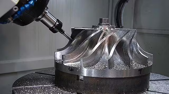
Five-axis motion removes most of those extra setups. Two rotary axes tilt either the tool or the table, so the cutter can approach a face from an angle without unclamping. On a simultaneous five-axis center, all five axes interpolate at once. That is what lets a single tool sweep a ruled surface on a turbine blade or blend a port into a manifold wall.
The practical gain is not only fewer setups. It is also shorter tools. A tilted tool reaches a deep pocket with less overhang than a straight one, and less overhang means less deflection. On a 12 mm end mill, cutting a 40 mm deep pocket, moving from 60 mm overhang to 35 mm can cut tool-tip deflection by roughly half. That shows up directly in wall straightness.
- 13-axisPrismatic parts, open faces, one dominant direction of features.
- 23+2 (positional)Angled faces reached by indexing the table, then cutting in a fixed pose.
- 3Simultaneous 5-axisContoured surfaces, blended ports, deep cavities with short tools.
- 4Mill-turnParts that are mostly round but carry milled flats, slots or cross holes.
Tolerance, finish and the error budget behind them
Tolerance is a budget, not a single number. Machine positioning, thermal drift, tool wear, fixturing and probing all draw from it. A shop that quotes ±0.005 mm is quoting the tightest band it can hold under controlled conditions, not a default for every feature on the drawing. Most features should sit looser, because every tightened band adds inspection time and scrap risk.
Surface finish follows the same logic. As-machined surfaces land around Ra 1.6–3.2 μm. A finer finishing pass with a smaller stepover reaches Ra 0.8–1.6 μm, and polishing or lapping gets to Ra 0.2–0.8 μm. Finer finish means slower feed and more passes, so it costs time. Call out finish only on the faces that seal, slide or carry optical function.
Thermal behavior matters more than most drawings admit. Aluminum expands about 23 μm per meter per °C. A 500 mm part that warms 5 °C during roughing grows roughly 58 μm before finishing even starts. Machines that hold ±0.005 mm do it with temperature-controlled coolant, warm-up cycles and sometimes a climate-controlled room. In-process probing then closes the loop on the actual part.
- 1Tightest practical band±0.005 mm on critical features, with probing and a controlled environment.
- 2Typical production band±0.025 mm to ±0.05 mm, which covers most mating and locating features.
- 3When to loosenNon-critical clearance holes, cosmetic faces, and any dimension with a large stack.
- 4Inspection100% inspection before shipment, with raw material, in-process and final checks.
Material behavior decides which process fits
The same geometry can be easy in one alloy and miserable in another. Aluminum 6061 and 7075 cut fast and hold a good finish. Stainless 304 work-hardens under a dull edge, so the cutter has to stay sharp and keep moving. Titanium Ti-6Al-4V carries heat into the tool instead of the chip, which is why it runs at lower surface speed and floods coolant.
Nickel alloys like Inconel push this further. They keep strength at high temperature, so they resist the cut. Tool life drops, cycle time rises, and the part may need a stress-relief step between roughing and finishing. That sequence is not optional on thin walls. Skip it and the part moves after the last pass.
Plastics bring their own rules. PEEK and POM machine cleanly with sharp, polished flutes and high spindle speed. ABS and PC soften and smear if the feed is too slow. Carbon fiber is worse: the abrasive fibers eat carbide edges, so diamond-coated tools are common. On any of these, the alloy choice is a machining decision before it is a design decision.
- 1Aluminum6061, 6061-T6, 2024, 5052, 5083, 6063, 6082, 7075, ADC12.
- 2Stainless303, 304, 316, 316L, 420, 430, 431, 440C, 17-4PH.
- 3Steel1018, 1045, 4130, 4140, 4340, A36, tool steel.
- 4Titanium and specialTA1, TA2, TC4, Inconel, magnesium AZ31B / AZ91D.
Machine envelope, batch size and finishing in one flow
Part size narrows the machine list quickly. A 4,000 mm maximum processing size needs a bed mill, not a 500 mm VMC. Rotary work changes the math too: a Ø400 mm rotary table limits how far a part can be indexed before it swings into the enclosure or loses rigidity at the edge of the table.
Batch size is the other filter. There is no minimum order quantity here, so one prototype and a 10,000+ part run both go through the same process plan. Prototypes are usually cut from billet on a five-axis center so the geometry can be checked without tooling cost. As volume climbs, it is worth comparing against die casting, vacuum casting or sheet metal fabrication, because those change the cost curve.
Finishing often decides whether a part can ship at all. Anodizing, plating, powder coating, bead blasting, polishing and laser marking all change dimensions by small amounts. Hardcoat anodize builds roughly half into the surface and half into the part, so a tight bore may need masking or a pre-machine allowance. Plan the finish at the drawing stage, not after the last cut.
- 1Large travel4,000 × 400 × 150 mm for long, slender parts.
- 2Medium travel750 × 1,150 × 550 mm and 600 × 600 × 600 mm.
- 3Compact travel500 × 500 × 450 mm and 500 × 310 × 200 mm.
- 4FinishesAnodizing, electroless nickel, plating, powder coat, blasting, laser marking.
When high-tech CNC machining solutions are the wrong choice
Subtractive machining is not always the answer. A thin-walled enclosure in 0.8 mm steel belongs in sheet metal, where the material is formed rather than carved away. A hollow duct with internal ribs may print faster than it machines. A simple round bushing in high volume is a screw-machine or casting job, not a five-axis one.
Cost is the second signal. If a part needs a long, slender tool to reach a deep feature, the tool will chatter and the cycle will crawl. Redesigning that feature, splitting the part, or switching to an additive-then-finish route can beat brute force. The right question is not which machine is most advanced, but which process reaches the tolerance with the fewest risky operations.
Lead time follows from that decision. Quotation and free DFM analysis come back within 12 hours, and production can start within 24 hours once the drawing and finish are settled. Parts ship in 3–5 days. Those numbers only hold when the process choice is sound. A part that fights its process will miss every date after that.
- 1Use sheet metalThin walls, large flat panels, formed flanges, low tooling cost.
- 2Use 3D printingInternal channels, lattice, or geometry a cutter cannot reach.
- 3Use castingHigh volume with a shape that releases from a mold.
- 4Stay with machiningTight tolerances, dense features, and surfaces that must seal or slide.
Choosing a process by part and volume
Use this as a first filter. The right column is the deciding factor.
| Part signal | Process to pick | Why |
|---|---|---|
| Angled faces, blended ports | Simultaneous 5-axis | One setup, short tools, no fixture stack-up |
| Round part with milled flats | Mill-turn | Turning and milling in one clamping |
| Thin 0.8 mm steel panel | Sheet metal fabrication | Forming beats carving on thin stock |
| Internal cooling channels | Custom 3D printing | A cutter cannot reach an enclosed path |
| One-off prototype | Rapid prototyping | No tooling cost, geometry checked early |
| 10,000+ simple housings | Metal die casting | Mold cost spreads over high volume |
| Sealing or sliding faces | CNC milling and turning | Tolerance and finish control per feature |
Pick the process that reaches the tolerance with the fewest risky operations
If the part carries angled features or blended surfaces and the volume is low, choose five-axis machining: one setup removes fixture error and lets you use a shorter, stiffer tool. If the part is thin, hollow, or molded by shape, choose sheet metal or casting and keep machining for the critical faces. Five-axis is the wrong answer when a formed or molded shape already meets the tolerance.
Questions engineers ask before releasing a drawing
How tight a tolerance can a five-axis machine actually hold?
±0.005 mm is the tightest practical band, and it applies to critical features only. It depends on a temperature-controlled environment, a warm-up cycle, sharp tooling and in-process probing.
Most dimensions on the same part should sit at ±0.025 mm to ±0.05 mm. Tightening every callout adds inspection time without improving function.
Why does surface finish cost so much?
A finer finish needs a smaller stepover and a slower feed, so the finishing pass takes longer and consumes more tool life. As-machined surfaces sit around Ra 1.6–3.2 μm.
Call out Ra 0.8–1.6 μm only on faces that seal, slide or carry optical function. Everywhere else, the standard finish is enough.
When should I split one part into two?
Split when a feature needs a tool so long that it chatters, or when a deep cavity has no room for chip evacuation. Two parts with a locating joint often machine faster and hold tolerance better than one deep pocket.
The joint adds assembly, so weigh that against the cycle time and scrap risk you remove.
Does the finish change my dimensions?
Yes. Anodizing, plating and coating all add or remove material. Hardcoat anodize builds roughly half into the surface and half into the part, which can close a tight bore.
Decide the finish before the last cut so the shop can leave a pre-machine allowance or mask the feature.
What happens between quote and first part?
Quotation and free DFM analysis come back within 12 hours. Production can start within 24 hours once the drawing, material and finish are confirmed.
During DFM we flag features that will drive cost or risk, such as deep slots, thin walls and tolerances tighter than the part needs.
How is confidentiality handled on new designs?
Uploads are secure and confidential. A non-disclosure agreement is available on request before files are shared.
We hold ISO 27001:2022 for information security, alongside ISO 9001:2015, IATF 16949:2016 and ISO 13485:2016.
Send the drawing and get a real process answer
Upload your files and an engineer reviews the geometry, tolerance and finish, then comes back with a quote and DFM notes within 12 hours.
12-hour quote100% inspectionNo minimum order quantity
More process notes from the shop floor
We publish setup notes, tooling trials and inspection data from the factory floor.











