
How CNC Machine Works
This guide explains how CNC machine works in a job shop, from CAD file to inspected part. It is written for design engineers and buyers who need to judge a process before they release a drawing. After reading it, you can read a G-code program, pick realistic tolerances, and spot setups that will fail.
In this article
- 1
- 2
- 3
- 4
- 5
- 6
- 7
Key takeaways
How CNC Machine Works: From Block to Finished Part
CNC stands for computer numerical control. A machine tool moves a cutting tool along coordinates that a computer gives it. Nothing is cast or molded. A solid block of aluminium, steel, or plastic goes in, and a smaller finished part comes out. The operator does not turn handwheels; the controller reads a program and drives the axes.
Three motions do most of the work. The spindle rotates the cutter. The linear axes move the workpiece or the tool in X, Y, and Z. On multiaxis machines, one or two rotary axes tilt either the tool or the part. Add coolant and chip evacuation, and you have a complete cutting system.
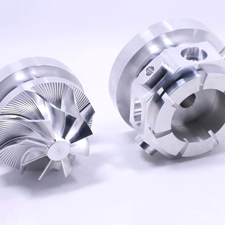
The important consequence for engineers is this: geometry is limited by tool access, not by a mold. Undercuts, deep pockets, and compound angles that a casting cannot release are normal work for a 5-axis machine. The trade-off is cycle time. Every pocket is cut line by line, so material removal rate drives cost.
A part that is easy to model is not always easy to machine. Long, thin tools deflect. Deep holes need peck drilling. Hard materials push tool wear up and feed rates down. Understanding how CNC machine works means knowing where those limits sit before you finalize the drawing.
- 1Additive vs subtractiveCNC removes material; 3D printing adds it layer by layer. CNC wins on density, surface finish, and tight tolerances.
- 2Milling vs turningMilling uses a rotating cutter against a stationary part. Turning rotates the part against a stationary tool.
- 33-axis vs 5-axis3-axis cuts one face per setup. 5-axis reaches five faces in one setup with less re-fixturing error.
What a G-code Program Actually Tells the Machine
A G-code file is a list of blocks. Each block has a line number, a motion command, coordinates, and feed or speed values. G00 moves fast to a position without cutting. G01 feeds in a straight line at the programmed rate. G02 and G03 cut arcs. M-codes handle spindle on, coolant on, and tool changes.
Feeds and speeds come from the material and the cutter. A 10 mm carbide end mill in 6061-T6 aluminium might run at 8,000 rpm and 2,500 mm/min. The same cutter in 316 stainless drops to around 1,200 rpm and 300 mm/min. Get this wrong and you either burn the tool or chatter the wall.
Modern controllers let the CAM programmer set feed per tooth, not just feed per minute. Feed per tooth is the chip thickness each cutting edge takes. Too small a chip rubs the edge and work-hardens stainless. Too large a chip overloads the flute. The sweet spot depends on cutter diameter and material.
You do not need to write G-code by hand to judge a quote. But reading the first twenty lines tells you the setup: which tool is loaded, where the work offset sits, and whether the programmer is roughing conservatively. That is often enough to explain a long cycle time.
- 1G00Rapid positioning move, no cutting.
- 2G01Linear cut at the programmed feed rate.
- 3G43Applies tool length compensation so Z heights stay correct.
Workholding and Datum Choice Drive Real Accuracy
The stiffest machine in the shop still cuts a bad part if the block moves. Workholding options run from a vise and soft jaws to a vacuum plate, a 3-jaw chuck, or a custom fixture. For thin-walled aluminium parts, soft jaws machined to the part profile spread the clamping load and stop the wall from bowing.
Datum selection is the design decision that most affects the result. A datum is the surface the programmer uses as zero. Pick a machined face, not a raw saw-cut edge, and keep the datum consistent from operation one through operation five. When the datum shifts, every downstream feature shifts with it.
Multiple setups introduce stacking error. Each re-clamp can add 0.02 to 0.05 mm of positional drift. That is why a part with bores on four sides is often cheaper on a 5-axis machine than on three separate 3-axis setups. Fewer setups means fewer chances to lose the position.
Thermal growth matters on long runs. A spindle warms up over the first hour, and a 500 mm steel part can grow with it. Shops that hold ±0.005 mm run warm-up cycles and check the first article after the spindle has stabilized, not on a cold machine.
- 1Rigid beats cleverA simple vise on a solid block outperforms a flexible fixture on a thin plate.
- 2One datum per drawingState it on the print and the machinist will hold it through every operation.
- 3Support the floorUnsupported floors vibrate and leave chatter marks at the bottom of a pocket.
Tolerance, Surface Finish, and What They Cost
Tolerance and surface finish are the two numbers that move price most. A general machining tolerance of ±0.1 mm on a milled aluminium bracket is routine. Tightening one bore to ±0.005 mm adds a finishing pass, a reaming or boring operation, and a CMM check. The cost sits in the extra time, not the material.
Surface finish is measured as Ra, the arithmetic mean roughness. As-machined finish on aluminium lands around Ra 1.6–3.2 μm. A finer pass with a sharper cutter and lighter depth of cut reaches Ra 0.8–1.6 μm. Below Ra 0.8 μm usually needs a polishing or lapping step after machining.
Not every surface needs the tight callout. Engineers who mark an entire print as ±0.01 mm pay for inspection across every feature. Mark only the functional surfaces, usually bearing bores, seal grooves, and mating faces. Leave the rest at general tolerance and the quote drops quickly.
Material choice sets the floor. Aluminium 6061-T6 machines fast and holds a good finish. 316L stainless work-hardens and needs slower speeds. Titanium Ti-6Al-4V and Inconel generate heat at the cutting edge and can need special tooling and more passes for the same geometry.
- 1±0.005 mmAchievable on critical features with correct tooling and inspection.
- 2Ra 0.8–1.6 μmStandard high-quality machined finish on aluminium and mild steel.
- 3Ra 0.2–0.8 μmFine finish, often followed by polishing on visible surfaces.
How CNC Machine Works: The 7 Steps of a Job
Follow this order and most surprises disappear before the first chip is cut.
- 11. Review the CAD file and DFMCheck wall thickness, corner radii, and tool access. A pocket corner tighter than the cutter radius cannot be cut square; it will come out as an arc. Minimum inside radius should be at least half the tool diameter. Flag thin floors under 1 mm and deep slots with a depth over four times the cutter diameter.
- 22. Choose stock and datumPick the blank size with 2–3 mm of allowance per machined face. Aluminium plate 6061-T6 is the default for prototypes. Set the datum on a face that will be machined early, and note it on the setup sheet so every operator uses the same zero.
- 33. Build the CAM toolpathsRough with a larger cutter to clear bulk material, then finish with a smaller one. Use trochoidal or high-efficiency paths in hard materials to control radial engagement. Leave 0.2–0.3 mm of stock for the finishing pass. Simulate the full program and check for holder collisions before posting.
- 44. Post-process to G-codeThe post-processor converts toolpaths into machine-specific code, including tool numbers, offsets, and safe Z heights. Verify the units match the drawing; a metric program run on an inch setup scraps the part on the first move. Confirm the correct work offset is called in the header.
- 55. Set up the machine and prove the programLoad the tools, touch off the offsets, and run the first part in single-block mode with rapid override down. Watch the distance-to-go readout rather than the cutter. On a new program, dry-run above the stock first. This catches a wrong offset before it becomes a crash.
- 66. Cut, monitor, and adjustListen for chatter and watch chip color. Blue chips in steel mean the speed or feed is too aggressive. Long stringy chips in aluminium mean the feed is too light. Adjust feed override in 10% steps and re-check the first few features with calipers before letting the run continue.
- 77. Inspect and releaseMeasure critical features against the drawing, not against the CAM model. Check bore sizes, flatness, and position. Record results on a first-article report. Parts ship only after 100% inspection, with dimensional reports available on request.
Choosing the Right Setup for the Part
Match the geometry to the machine before you ask for a quote.
| Part feature | Best setup | Typical tolerance | Watch out for |
|---|---|---|---|
| Flat plate, holes on one face | 3-axis mill | ±0.05 mm | Thin plate lifting in the vise |
| Bores on four sides | 5-axis or 4-axis with tombstone | ±0.01 mm | Stacking error from extra setups |
| Cylindrical shaft with flats | Mill-turn center | ±0.01 mm | Runout between turning and milling |
| Deep pocket, 4× diameter | 3-axis with long reach cutter | ±0.05 mm | Tool deflection and chatter |
| Compound angle port | Simultaneous 5-axis | ±0.01 mm | Holder collision in the pocket |
| Thin wall under 1 mm | Soft jaws, light finishing pass | ±0.05 mm | Wall bowing under clamp load |
| Hardened tool steel insert | 3-axis with carbide, slower feed | ±0.01 mm | Tool wear mid-run, size drift |
Know the limits before you release the drawing
CNC rewards parts designed for tool access, rigid setup, and realistic tolerances. Send us your model and we will return a DFM analysis with the changes that cut cost without touching function.
Questions Engineers Ask About CNC Machining
Do I need to supply a 3D model or will a 2D drawing work?
A 3D STEP file is the fastest route. CAM software reads it directly and generates toolpaths without interpretation.
A 2D drawing works for simple turned parts, but complex surfaces need a model. If you only have a PDF, we can quote from it and flag any feature that needs clarification before cutting.
What is the smallest feature a CNC machine can cut?
It depends on the cutter. Micro end mills down to 0.5 mm are available, but they break easily and cut slowly. A practical floor for production work is a 1 mm cutter, which gives an inside corner radius of about 0.5 mm.
Text and engraving can go smaller. Laser marking on our parts holds a minimum character height of 1.5 mm.
How tight a tolerance should I put on the drawing?
Start with a general tolerance of ±0.1 mm and tighten only the features that matter. Bearing bores, seal seats, and mating faces are the usual candidates.
Tightening every dimension multiplies inspection time. We can reach ±0.005 mm on critical features, but that callout should be deliberate.
How long does a CNC run take from quote to delivery?
We return a quotation and free DFM analysis within 12 hours. Production can start within 24 hours of approval, and parts ship in 3–5 days for most jobs.
Complex 5-axis work or parts needing a special finish can take longer. We confirm the schedule at the quote stage, not after the order.
Can you machine prototypes and full production runs on the same process?
Yes. There is no minimum order quantity, so one prototype and a 10,000-part run use the same process and the same inspection standard.
Keeping both on CNC avoids a process change between validation and production, which is where many tolerance surprises come from.
What materials and finishes do you cover?
Aluminium 6061, 7075, and 2024; stainless 303, 304, 316L, and 17-4PH; steels including 4140 and 4340; titanium Ti-6Al-4V; and engineering plastics such as POM, PEEK, and PC.
Finishes include anodizing, electroless nickel, zinc and silver plating, powder coating, black oxide, bead blasting, and laser marking.
Upload your design and get a quote in 12 hours
Send a STEP file for a free DFM review. No minimum order quantity, from one prototype to 10,000+ parts.
12-hour quote100% inspectionNDA on requestNo MOQ
More from GreatLight
We publish setup notes, tooling trials and inspection data from the factory floor.











