
How Do You Use a CNC Machine?
A walkthrough of the full cycle: read the drawing, choose the machine, set the zero, prove the program, cut, inspect. Written for design engineers and buyers who need to judge a part before it reaches the floor. By the end you should know which features fit a 3-axis mill and which ones force a 5-axis setup.
In this article
- 1
- 2
- 3
- 4
- 5
- 6
- 7
- 8
Key takeaways
What Happens Before You Use a CNC Machine
A CNC machine does not decide anything. It repeats a path that someone already proved. So the real work starts at the drawing: you need the material, the blank size, the datums, the tightest tolerance and the surface finish on each face. A part with ±0.005 mm on one bore and ±0.1 mm everywhere else is a different job from a part that is tight all over.
Next comes the setup plan. Ask how many orientations the part needs. A plate with holes on one face is a single 3-axis setup. A part with features on four sides plus a compound angle usually needs a 4-axis or 5-axis machine, or two or three refixtures on a 3-axis. Every extra refixture adds stack-up error, so the axis count follows the setup count, not the other way around.
Then the CAM programmer builds the toolpath from the CAD model and posts G-code. Tool choice drives the rest: a Ø10 mm carbide end mill can rough aggressively but cannot enter a 6 mm corner. A Ø3 mm tool reaches the corner but must run slower and deflects more. If a corner radius is smaller than the smallest tool you are willing to run, the design should change before the machine runs.
Finally, the machine itself. A vertical mill handles prismatic parts. A lathe or mill-turn center handles round parts with turned diameters and milled flats. Wire EDM handles sharp internal corners and hardened steel. Knowing which process owns the feature saves a quote cycle.
- 1Drawing firstMaterial, datums, tightest tolerance and finish on each face.
- 2Setup countEach additional orientation adds stack-up error.
- 3Tool reachSmallest internal radius sets the smallest cutter.
Choosing the Machine and Workholding
For prismatic parts, a 3-axis vertical mill covers most work. Typical travels are 500 × 500 × 450 mm or 750 × 1,150 × 550 mm, which suits brackets, housings and plates. A 4-axis mill adds a rotary table, usually Ø400 mm, so you can index the part to a second or third face without touching the vise. That single addition often removes two refixtures.
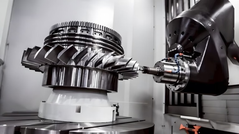
Simultaneous 5-axis centers cut compound angles and contoured surfaces in one pass. They also let a short, stiff tool reach deep pockets by tilting the part instead of hanging the tool out. The trade-off is programming time and a smaller work envelope, so reserve them for parts that genuinely need the motion. Turning work goes to a lathe or mill-turn center, where a single setup can turn an OD and mill a flat.
Workholding decides whether the part moves. A vise is fast but leaves two faces open and can distort thin walls. Soft jaws machined to the part profile grip round or irregular shapes without crushing them. For thin plates, vacuum chucks or a fixture plate with toe clamps spread the load. For a second operation on a finished face, use a fixture that locates on a machined datum, never on the raw stock.
One rule: never clamp on a surface that has a tolerance callout unless that surface is supported underneath. Clamping pressure of a few hundred newtons is enough to spring a 2 mm wall, and the part will spring back after unclamping, out of tolerance.
- 1ViseFast, but leaves two faces open and can distort thin walls.
- 2Soft jawsMachined to the part profile; grips without crushing.
- 3Fixture plateLocates on a machined datum for the second operation.
Setting the Work Zero and Tool Offsets
The work zero is the point the program calls X0 Y0 Z0. Pick it from the drawing datums so the machine coordinates match the inspection coordinates. If the drawing dimensions a bore from a machined face, that face is your Z0, not the top of the raw stock. Getting this wrong shifts every dimension by the same amount, and the part will look correct but measure wrong.
Touch off each tool to a known surface and store the length in the offset table. A probe makes this repeatable to a few microns; a dial indicator and a gauge block still work but take longer. After touching off, verify by commanding the tool to a safe height above the stock and comparing the readout with a gauge block or a height setter.
Record the work offset and tool numbers on the setup sheet. The next operator should be able to reload the vise and the offsets without re-measuring from scratch. This is also what makes a repeat order fast: the fixture, the program and the offsets already exist.
If the machine has no probe, note the spindle warm-up. A cold spindle grows as it heats, and a Z offset set on a cold machine can drift 0.02 mm or more over the first hour. Warm up the spindle for 10 to 15 minutes before touching off on work that holds a tight tolerance.
Feeds, Speeds and the First Cut
Start from surface speed, not spindle RPM. Aluminium 6061 runs well at 300 to 500 m/min with carbide, which on a Ø10 mm tool gives roughly 10,000 to 16,000 rpm. Steel 1045 runs at 100 to 150 m/min, so the same tool turns at about 3,000 to 4,800 rpm. Titanium TC4 sits lower still, around 40 to 60 m/min, because the heat stays in the cutting edge.
Feed per tooth sets the chip load. For a Ø10 mm carbide end mill in aluminium, 0.05 to 0.10 mm per tooth is a normal range; in steel, 0.03 to 0.06 mm per tooth. Multiply feed per tooth by the tooth count and the rpm to get the feed rate, and check that the chip is a proper chip, not dust. Dust means the tool is rubbing and will wear fast.
For roughing, take depth of cut up to the tool diameter when the setup is rigid, and leave 0.3 to 0.5 mm on walls and floors for the finishing pass. Finishing with a small radial stepover, around 5 to 10% of the tool diameter, gives Ra 0.8–1.6 μm on most aluminium. A Ra 0.2–0.8 μm mirror finish needs a dedicated finishing tool and a rigid setup.
Coolant choice matters. Flood coolant controls heat in steel and stainless. Aluminium often cuts better with a mist or high-pressure air because it clears chips and avoids thermal shock on the edge. Titanium and Inconel need high-pressure coolant aimed at the cutting zone to break chips and protect the insert.
- 1Aluminium 6061300–500 m/min with carbide; 0.05–0.10 mm per tooth.
- 2Steel 1045100–150 m/min; 0.03–0.06 mm per tooth.
- 3Titanium TC440–60 m/min; high-pressure coolant at the edge.
Errors That Scrap the First Part
The most common failure is the wrong Z zero. An operator touches off on the top of the raw stock when the drawing dimensions from a machined step. Every depth is then short or long by the stock allowance. The fix is written on the setup sheet: state the datum face in words, not just a coordinate.
Second is tool deflection on deep pockets. A Ø6 mm end mill hanging 40 mm out of the holder will bend under load, and the wall will taper. Listen for chatter and reduce the axial depth or use a shorter tool. If neither works, the pocket needs a different process, such as EDM or a relieved tool holder.
Third is clamping distortion. A thin wall clamped at 300 N will move by tens of microns, and the part springs back after unclamping. Support the wall from behind, reduce clamp pressure, or machine the wall in a finishing pass after the clamps are relaxed. Measure a suspect wall while it is still clamped and again after, and compare.
Fourth is chip recutting. If chips stay in the pocket, the tool cuts them instead of the workpiece and the finish turns ragged. Use through-spindle coolant, air blast or a peck cycle that lifts the tool clear. On aluminium, a strong air blast often works better than flood coolant because it clears chips faster.
How to Use a CNC Machine: Step by Step
Follow in order. Each step has a check you can pass or fail before moving on.
- 1Read the drawing and mark the datumsList material, blank size, tightest tolerance and finish per face. Circle the datums that the inspection plan will use. Fail this step and every dimension downstream is referenced to the wrong face.
- 2Choose the machine and fixtureCount orientations. One or two means a 3-axis or 4-axis mill; compound angles mean 5-axis. Select a vise, soft jaws or a fixture plate, and confirm the part fits the travels with clearance for the tool holder.
- 3Build the CAM programImport the CAD model, set the stock, and pick tools by the smallest internal radius. Use 0.3 to 0.5 mm finishing stock. Post the G-code and read the first 20 and last 20 lines before sending it to the machine.
- 4Set the work zero and tool offsetsTouch off on the datum faces, store the offsets, and verify with a gauge block. Warm up the spindle 10 to 15 minutes first if the tolerance is tighter than 0.02 mm.
- 5Dry run with Z raisedRaise the Z offset by 50 mm and run the program. Watch the rapid moves and listen for the tool path. Any unexpected plunge is a programming error, not a machine error.
- 6Cut the first part and measureRun the program, then measure the critical dimensions while the part is still clamped. Correct with wear offsets before unclamping if the error is small and repeatable.
- 7Deburr and inspectHand-deburr edges and check every tolerance against the drawing. Record the actual values on the inspection report.
- 8Run production with in-process checksCheck the first part, then sample at a set interval. A tool that holds ±0.005 mm at minute one may drift after an hour of continuous cutting.
Which Machine Setup Fits Which Part
Match the part geometry on the left to the setup that reaches it.
| Part feature | Typical setup | What to watch |
|---|---|---|
| Holes on one face only | 3-axis mill, one vise setup | Hole depth versus tool reach |
| Features on two or three faces | 3-axis with a second refixture | Datum repeatability between setups |
| Features on four sides | 4-axis mill with Ø400 mm rotary table | Rotary centerline alignment |
| Compound angles, contoured surfaces | Simultaneous 5-axis center | Programming time; work envelope |
| Turned OD plus milled flats | Mill-turn center, one setup | Chuck pressure on thin walls |
| Thin plate, 2 mm wall | Vacuum chuck or fixture plate | Clamp pressure and spring-back |
| Sharp internal corner, hardened steel | Wire EDM after milling | Corner radius the mill cannot reach |
The short answer
You use a CNC machine by fixing the part so it cannot move, defining one zero that matches the drawing datums, proving the program in the air, then cutting and measuring before you unclamp. Get the setup right and the cutting data becomes routine.
Questions Engineers Ask
Do I need G-code experience to use a CNC machine?
No. CAM software writes the G-code from the CAD model. What you do need is the ability to read the posted program enough to spot a wrong offset, a missing tool change or a rapid move into the part.
At GreatLight the programmer and the machine operator are different people, and the setup sheet carries the offsets and datum notes so the program can be reloaded without re-measuring.
How tight a tolerance can a normal CNC mill hold?
Work with a ±0.005 mm capability when the setup is rigid, the tool is short and the temperature is stable. That is ±0.0002 in.
Tighter than that becomes a grinding or lapping operation, and the inspection method has to match: a caliper will not verify a micron.
What surface finish can I expect from milling?
As-machined surfaces land at Ra 1.6–3.2 μm. A controlled finishing pass reaches Ra 0.8–1.6 μm, and a dedicated finishing strategy with a small stepover can reach Ra 0.2–0.8 μm.
Finish also depends on the material. Aluminium finishes cleanly; gummy stainless and titanium need sharper edges and better coolant.
When should I not use a CNC machine?
Very thin sheet with large flat areas is usually faster on a laser or a press brake. A sharp internal corner in hardened steel belongs on wire EDM. A hollow, complex internal channel with no straight access belongs on 3D printing or casting.
CNC wins on prismatic parts with tight tolerances, good surface finish and a need for repeatability from one part to the next.
Can you machine one piece, or is there a minimum order?
No minimum order quantity. We run from one prototype to 10,000+ part runs, and the same fixture and program carry from prototype into production.
Uploads are secure and confidential, and an NDA is available on request.
How fast can a first article be cut?
Quotation and free DFM analysis come back within 12 hours. Production can start within 24 hours, and parts ship in 3–5 days.
These figures assume the drawing is complete and the material is in stock. A missing tolerance callout adds a review cycle before the program is posted.
Send the drawing and we will tell you how to machine it
DFM feedback inside 12 hours, from one prototype to a 10,000-piece run, with 100% inspection before shipment.
12-hour quote±0.005 mm100% inspectionNDA on request
More from the shop floor
We publish setup notes, tooling trials and inspection data from the factory floor.











