
How Does a CNC Machine Operate?
A CNC machine reads a program, moves a spindle along a planned path, and cuts metal or plastic to a drawing. This page walks through the full cycle for engineers and buyers who need to judge setups, tolerances and where a run can go wrong. Read it before you approve a process sheet.
In this article
- 1
- 2
- 3
- 4
- 5
- 6
- 7
- 8
- 9
Key takeaways
How does a CNC machine operate from drawing to chip?
A CNC machine does not think about the part. It executes a list of coordinates. The list comes from CAM software that turns a 3D model into toolpaths, then posts them as G-code for a specific controller. On a typical 3-axis mill, that code might contain 8,000 to 40,000 lines for one housing.
The machine's job is to move a spinning tool through material at a controlled rate while holding the workpiece still. Feed rate, spindle speed, depth of cut and tool geometry set how the metal leaves the block. Get one of those wrong and you get chatter, a broken tool, or a scrapped part.
Everything before the first cut is preparation. Fixture design, datum selection, tool list and stock size all happen offline. On the floor, the operator loads the program, sets work offsets, touches off tools, and runs a dry pass with the spindle clear of the part.
- 1InputSTEP or IGES model, 2D drawing, material spec, tolerance callouts
- 2OutputFinished part, chip bin, inspection report
- 3Cycle time driversMaterial removal rate, tool changes, number of setups
CAM planning and toolpath strategy before the spindle turns
A programmer opens the model and decides how to hold it. That single decision shapes the rest of the job. A part clamped on 6 mm of stock will deflect under a 12 mm end mill at 2 mm depth of cut. Clamp it across 20 mm and the same cut runs clean.
Toolpath strategy follows. Roughing removes 60–80% of the stock with a large tool, typically a 12–20 mm carbide end mill at 0.5–1.5 mm radial engagement. Finishing follows with a smaller tool, often 6–10 mm, and lighter passes. For aluminium 6061, surface speeds of 300–500 m/min are normal; for 316 stainless, drop to 120–180 m/min.
The programmer also chooses the work coordinate system. On a 3-axis mill, that is usually a corner or a bore on the stock. On a 5-axis machine, the datum may sit on the part itself so the same zero works across several orientations. Every extra datum is another chance for a stack-up error.
Post-processing converts the toolpath into controller-specific code. Fanuc, Siemens and Heidenhain all read G-code, but canned cycles and tool-change macros differ. A program posted for the wrong controller will alarm out or, worse, rapid into the fixture.
- 1Stock allowance0.3–0.8 mm per side for finishing after heat treatment
- 2Tool stick-outKeep under 4× diameter to limit deflection
- 3Coolant modeFlood for steel, through-spindle for deep holes, air blast for plastics
What happens inside the machine during a cut
The controller reads the program block by block. Each block commands axis motion, spindle speed, feed, or a tool change. Servo motors drive ball screws that position the table and spindle to within ±0.005 mm on a well-maintained machine. Linear scales on higher-end machines close the loop directly on the slide.
At the cutting edge, the tool shears material ahead of the flute. Most of the heat leaves with the chip. That is why chip evacuation matters as much as coolant flow. A nest of chips packed in a pocket will rub the tool, raise cutting temperature past 600 °C, and shorten tool life by half.
Tool changes happen automatically on machines with an automatic tool changer. A 20-pocket ATC swaps tools in 3–8 seconds. Operators monitor spindle load, sound and chip color. Blue chips on steel mean the speed is too high; silver chips with a squeal mean the feed is too low.
When the program ends, the spindle retracts and stops. The operator checks the part against the drawing before releasing the fixture. On tight-tolerance features, that check happens on a CMM rather than at the machine.
- 1Spindle loadKeep below 80% of rated power on roughing passes
- 2Chip colorSteel should come off grey to straw, not blue
- 3Air cutRun the first part 5–10 mm above the stock to verify path
How does a CNC machine operate differently by axis count?
A 3-axis mill moves X, Y and Z. The tool always points straight down. That is enough for plates, brackets and housings with features reachable from one or two sides. Setups are simple and cycle times are short.
A 4-axis machine adds a rotary table, usually around X or Y. The part rotates while the tool cuts, so you can machine four faces in one setup. This cuts fixture error and lets a single program drill, mill and slot around a shaft or a manifold block.
A 5-axis machine adds a second rotary axis, so the tool can approach the part from nearly any angle. Undercuts, deep pockets with drafted walls and compound angles become reachable without re-fixturing. The trade-off is programming time and a tighter setup window. A 5-axis job that is not planned well can run slower than two 3-axis setups.
- 13-axisPrismatic parts, flat datums, one or two setups
- 24-axisShafts, manifolds, parts with features on four sides
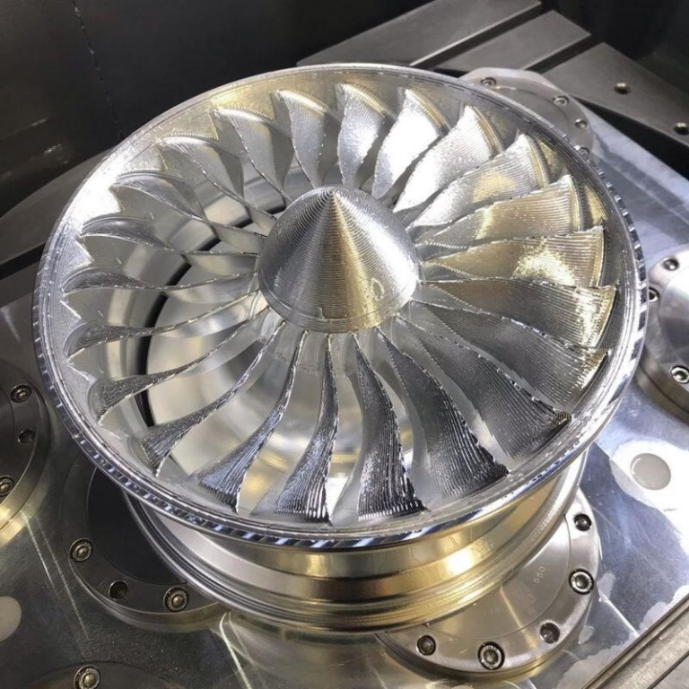
- 35-axisImpellers, medical implants, complex aerospace brackets
Material behavior changes the operating window
Aluminium 6061 cuts fast. A 12 mm carbide end mill can run at 4,000–8,000 rpm with a 3,000–6,000 mm/min feed in a rigid setup. The chips are light and the tool lasts. Plastics like POM and ABS need sharp tools, high rake angles and air blast, because heat builds up and melts the chip onto the cutter.
Stainless 316 work-hardens if the tool rubs. Keep the feed per tooth above 0.05 mm so the edge bites instead of sliding. Titanium Ti-6Al-4V is worse: it conducts heat poorly, so the edge sees 800 °C or more. Use low surface speed, 40–60 m/min, heavy feed and plenty of coolant.
Inconel and other nickel alloys sit at the hard end. Surface speeds of 20–35 m/min, rigid setups and ceramic or carbide tools with coatings are standard. If a job calls for Inconel and the fixture is light, no program will save it.
Hardness matters after heat treatment. A 4140 part at 28 HRC cuts cleanly with carbide. The same part at 52 HRC needs CBN or ceramic tooling and a machine with enough rigidity to avoid vibration.
- 1AluminiumHigh speed, high feed, air or flood coolant
- 2Stainless and titaniumLower speed, heavier feed, no dwelling on the cut
- 3PlasticsSharp edges, air blast, climb milling for finish
In-process checks and where a run drifts
Every machined run drifts. Tools wear, thermal growth moves the spindle, and chips pack into fixtures. The operator's job is to catch drift before it leaves the tolerance band. On a ±0.05 mm feature, checking every 20 parts is usually enough. On a ±0.005 mm bore, check every 5 to 10 parts or after any tool change.
First-article inspection sets the baseline. The operator measures all drawing dimensions on the first good part and records them. If a bore comes in at 10.012 mm against a 10.000 +0.015 mm callout, the offset is fine. If it comes in at 10.022 mm, adjust the tool offset before running the rest.
Temperature matters on tight work. A part measured at 35 °C will shrink when it cools to 20 °C. For aluminium, the change is about 0.023 mm per 100 mm per 10 °C. For steel, roughly half that. Let parts settle before final inspection, or measure and correct for temperature.
At GreatLight, inspection runs on raw material check, in-process monitoring and a final check before shipment. Reports are available on request. The shop runs to ±0.005 mm on critical features and holds a 99.99% qualification rate across production runs.
- 1First articleFull dimensional check before releasing the run
- 2In-processCheck wear-prone features every 5–20 parts
- 3Final100% inspection before shipment, reports on request
Step by step: running a CNC job from setup to sign-off
- 1Verify the program and setup sheetMatch program number, revision and fixture to the job packet. Check stock size and material cert. Wrong revision is the most common cause of a scrapped first part.
- 2Load and clamp the workpieceClean the vise jaws and fixture pads. Clamp with enough force to hold the part but not distort it. For thin walls, use soft jaws or a vacuum plate. Torque values around 20–40 Nm are typical for a 100 mm vise.
- 3Set work offsets and tool lengthsTouch off X, Y and Z to the datum called out on the setup sheet. Set each tool length with a presetter or a touch-off block. Record offsets so a crash does not force a full reset.
- 4Run a dry pass with the spindle clearRaise Z by 50 mm and run the program at rapid. Watch for any path that enters the fixture or clamps. Fix the program before cutting metal.
- 5Cut the first part and inspectRun at 70–80% of programmed feed for the first part. Measure all critical dimensions. Adjust tool offsets if any feature is out by more than 20% of its tolerance.
- 6Run production with in-process checksCheck wear-prone features every 5–20 parts, or after every tool change on tight-tolerance work. Log the readings.
- 7Deburr, clean and inspect final partsRemove sharp edges, wash off coolant, and run the final dimensional check. Pack parts with the inspection report if the customer requires it.
Machine setup trade-offs at a glance
Use this to decide which machine class fits a job before quoting.
| Factor | 3-axis | 4-axis | 5-axis |
|---|---|---|---|
| Typical part | Plate, bracket, housing | Shaft, manifold block | Impeller, implant, complex bracket |
| Setups per part | 1–3 | 1–2 | 1 |
| Fixturing complexity | Low | Medium | High |
| Programming time | Short | Moderate | Long |
| Reachable features | One direction plus sides | Four sides in one setup | Nearly all angles |
| Best tolerance window | ±0.01 mm | ±0.01 mm | ±0.005 mm |
| Typical lead time | 2–4 days | 3–5 days | 4–7 days |
The program is only half the job
A CNC machine operates on coordinates, but the part comes out right only when the fixture, offsets and tool wear are controlled. If your drawing has tight tolerances or hard materials, talk to the shop before the design is frozen. We review setups and give a DFM analysis within 12 hours.
Questions engineers ask about CNC operation
How does a CNC machine know where the part is?
The operator sets work offsets that tell the controller where the part datum sits in machine coordinates. On a mill, that is usually a corner or a bore on the stock. The program then references that datum for every move.
Tool length offsets tell the controller how far each tool tip sits from the spindle gauge line. Set them wrong and the first rapid move will drive the tool into the part or the vise.
What tolerance can a CNC machine hold in normal production?
A well-maintained 3-axis or 4-axis machine holds ±0.01 mm on features with stable fixturing. A 5-axis machine with linear scales can hold ±0.005 mm on critical features.
Tighter than that needs temperature control, in-process gauging and a CMM check. The machine is rarely the limit; the setup and thermal drift usually are.
Why does a CNC machine sometimes leave chatter marks?
Chatter comes from vibration between the tool and the workpiece. Common causes are too much tool stick-out, a light fixture, or a feed and speed combination that excites the tool's natural frequency.
Fix it by shortening the tool, stiffening the fixture, or changing spindle speed by 10–15%. On deep pockets, a smaller step-over and a climb-milling pass often clean up the wall.
Do I need a 5-axis machine for a part with angled holes?
Not always. A 3-axis machine with an angle plate or a sine vise can drill the same holes in a second setup. That setup costs less than a 5-axis program.
A 5-axis machine pays off when the part has many angled features, deep undercuts, or a tolerance stack that a second setup would break.
How long does it take to set up a CNC job?
A simple 3-axis job with one vise setup takes 30–60 minutes from stock load to first chip. A 5-axis job with a custom fixture and 12 tools can take 3–6 hours.
Setup time is a one-time cost per run. On a 10,000-part order it barely matters. On a 5-part prototype it can be half the quoted price.
What causes a CNC machine to cut undersize or oversize?
Tool wear is the usual cause on long runs. A 10 mm end mill can lose 0.02–0.05 mm of diameter over a few hundred parts in stainless. Check wear and adjust the offset.
Thermal growth moves the other way. A spindle that has run for four hours is longer than a cold one. On tight work, warm up the spindle for 15–20 minutes before the first cut.
Send your model, get a machinable answer
Upload a STEP file and we return a quotation with a free DFM analysis within 12 hours. Production can start within 24 hours, and parts ship in 3–5 days.
12-hour quoteNo minimum order±0.005 mm tolerance100% inspection
More from the shop floor
We publish setup notes, tooling trials and inspection data from the factory floor.











