
How to Build a 4 Axis CNC Machine
If you want to build 4 axis cnc machine setups that hold tolerance, start here. This guide covers frame layout, rotary table selection, and the alignment numbers that separate a usable machine from a loose one.
In this article
- 1
- 2
- 3
- 4
- 5
- 6
- 7
Key takeaways
What the fourth axis adds, and what it does not
A 3-axis mill moves the tool in X, Y, and Z. The workpiece stays clamped. A fourth axis adds a rotary table, usually the A axis, that turns the part around the X direction. Now the same tool can reach four sides of a block without a re-fixture. That is the whole gain. You are trading setup time for rotary accuracy.
The A axis is not a substitute for a trunnion or a 5-axis head. It turns the part but does not tilt the tool. So undercuts, deep cavities with overhanging walls, and true 5-face work still need more axes. For shafts with milled flats, cam profiles, and parts with features spaced around one centerline, a fourth axis is enough.
If you plan to build 4 axis cnc machine hardware, decide first what the machine must hold. A hobby router with a 100 mm chuck and a belt drive will hold maybe ±0.05 mm over a 150 mm part. A machined cast-iron table with a preloaded worm gear can hold ±0.01 mm. The rest of the frame has to match that number, or the rotary accuracy is wasted.
- 1Good fitShafts, bushings, cam plates, parts with radial hole patterns.
- 2Poor fitThin plates, large flat cavities, anything needing tool tilt.
- 3Check firstDoes the CAM post output A moves, or only X, Y, Z?
Frame and motion components that keep the fourth axis honest
Start with the base. Epoxy granite, welded steel filled with epoxy, or a thick cast iron plate all work. What matters is mass and damping. A base under 80 kg will ring when the rotary table indexes. Bolt the rotary table to a machined pad, not to a raw weldment. The pad face should be flat within 0.02 mm and parallel to the machine table within 0.03 mm.
For the linear axes, 25 mm or 30 mm profile rails are the common choice on a home build. Ballscrews of C7 grade are acceptable for hobby work; C5 ground screws are what you want if the A axis is ground to match. Belt drives on X and Y will show up as backlash in circular interpolation. If the part needs a smooth radial profile, use screws on all three linear axes.
The spindle matters more than most builders expect. A 2.2 kW water-cooled spindle at 24,000 rpm cuts aluminium well but has no torque at low speed. For steel you need a belt-driven spindle with a low ratio, or you accept light depths of cut. The rotary table and the spindle should be sized together. A 100 mm chuck cannot hold a part that a 2.2 kW spindle can rough at full load.
- 1Base massAim for 80 kg or more on a benchtop frame.
- 2Rail size25–30 mm profile rail, preloaded carriages.
- 3Screw gradeC7 rolled for hobby; C5 ground for tight radial work.
Choosing and mounting the rotary table
Three drive types cover most builds. A worm gear table gives high ratio and good holding torque, but the worm has backlash unless it is adjustable. A harmonic drive table is compact and near-zero backlash, but costs more and has a lower torque limit. A direct-drive servo table indexes fast and repeats well, but needs a brake to hold during cutting.
For a first build, an adjustable worm table in the 100–200 mm range is the practical pick. Check two numbers before you buy: backlash at the output flange, and runout of the chuck face. Backlash under 0.02 mm at the flange is workable. Chuck face runout over 0.03 mm will show on every part.
Mount the table so its centerline is parallel to the X rail. Indicate the chuck face and the table body. Adjust shims under the mounting pad until the error is under 0.02 mm over 300 mm of travel. Then indicate the chuck jaws at 90 degree intervals. If the runout changes as you rotate, the table or the chuck is not true and no amount of shimming will fix it.
- 1Worm driveCheap, high ratio, needs backlash adjustment.
- 2Harmonic driveLow backlash, higher cost, lower torque.
- 3Direct driveFast indexing, needs a brake for cutting.
Common build errors and how they show up
The first error is a rotary table bolted to an unmachined surface. The table looks square, but the centerline sits two tenths off over 200 mm. Every radial feature drifts. Fix it by machining the pad after the frame is welded, not before.
The second is mismatched steps per degree. The controller moves A in degrees, the driver is set for steps per revolution, and the ratio in the config is wrong. The machine cuts a hole pattern that looks round but is off by a fixed angle. Always calibrate with a 360 degree command and a dial indicator on the chuck.
The third is backlash left in the worm. Under light cuts it does not show. Under a 3 mm depth of cut in aluminium the table rocks and the surface shows chatter marks spaced at the tooth pitch. Adjust the worm engagement until backlash at the flange is under 0.02 mm, and recheck after 20 hours of running.
The fourth is a spindle too large for the table. A heavy spindle with a small chuck means the part moves before the tool does. Match the cutting load to the holding torque of the table, and use a tailstock when the part overhangs more than two diameters.
- 1Unmachined padCenterline drifts, radial features wander.
- 2Wrong steps per degreePattern is round but rotated by a fixed angle.
- 3Worm backlashChatter marks at the tooth pitch under load.
Step by step: building the machine
Follow the order. Checking alignment before the frame is bolted down wastes the measurement.
- 1Level and grout the baseSet the base on pads and level it to 0.02 mm per 1,000 mm in both directions. Let epoxy grout cure 24 hours before bolting anything to it.
- 2Mount the X and Y railsBolt rails to the machined pads and check straightness with a dial indicator. Aim for under 0.01 mm deviation over the full travel. Torque in a cross pattern.
- 3Fit the ballscrews and thrust bearingsPreload the angular contact bearings to a light drag. Check backlash at the nut: under 0.01 mm for C5, under 0.03 mm for C7.
- 4Install the spindle and tram itTram the spindle to the table within 0.02 mm over a 200 mm sweep. Recheck after the first hour of running; castings settle.
- 5Bolt down the rotary tableMount on the machined pad. Indicate the chuck face parallel to X to under 0.02 mm per 300 mm. Shim under the pad, not under the table feet.
- 6Wire the fourth driver and set the stepsMatch driver current to the motor rating, then set steps per degree. Calibrate by commanding a 360 degree move and reading the error with a dial indicator.
- 7Test with a known partCut a 100 mm diameter aluminium disc with four radial holes. Measure hole position and disc roundness. Adjust backlash compensation until the error is inside your target.
Build it or buy the machining time
Use this to decide whether the fourth axis belongs in your shop or in a supplier's schedule.
| Situation | Build in house | Send out | Reason |
|---|---|---|---|
| One-off prototype, tight tolerance | No | Yes | Alignment time exceeds part value |
| Repeat radial hole patterns | Yes | No | Setup pays back after a few parts |
| Aluminium parts under 200 mm | Yes | No | Light frame is enough |
| Steel parts over 300 mm | No | Yes | Needs mass and torque a home frame lacks |
| Parts needing tool tilt | No | Yes | A fourth axis cannot tilt the tool |
| Tolerance tighter than ±0.01 mm | No | Yes | Ground screws and metrology cost more than the build |
| Production runs of 1,000+ | Maybe | Yes | Supplier capacity and inspection reports |
Build it if the parts repeat. Buy the time if they do not.
A fourth axis pays back on recurring radial work. For one-off or tight-tolerance parts, a supplier with ground screws and metrology is the shorter path.
Questions builders ask
Can I add a fourth axis to an existing 3-axis mill?
Yes, if the controller has a spare driver channel and the post-processor supports A moves. You need a rotary table, a driver card, and a way to mount the table parallel to X.
Check the table weight against the machine table load limit. A 200 mm worm table can weigh over 40 kg.
What tolerance can a home-built fourth axis hold?
A well-aligned worm table with a machined pad can hold about ±0.01 mm on radial features over a 150 mm part. A belt-driven hobby setup is closer to ±0.05 mm.
The limit is usually the rotary table and the frame damping, not the controller.
Do I need a tailstock?
Yes when the part overhangs more than two diameters from the chuck. Without support the part deflects and the cut shows taper.
A simple live center in a tailstock block is enough for most shaft work.
How do I calibrate the A axis?
Command a 360 degree rotation and indicate a point on the chuck with a dial indicator. Read the error at the start and end position.
Adjust steps per degree until the error is inside 0.01 mm at the chuck radius.
When should I send the part out instead of building?
When the tolerance is tighter than ±0.01 mm, when the part needs tool tilt, or when it is a one-off prototype. Setup time on a new build is hard to justify for a single part.
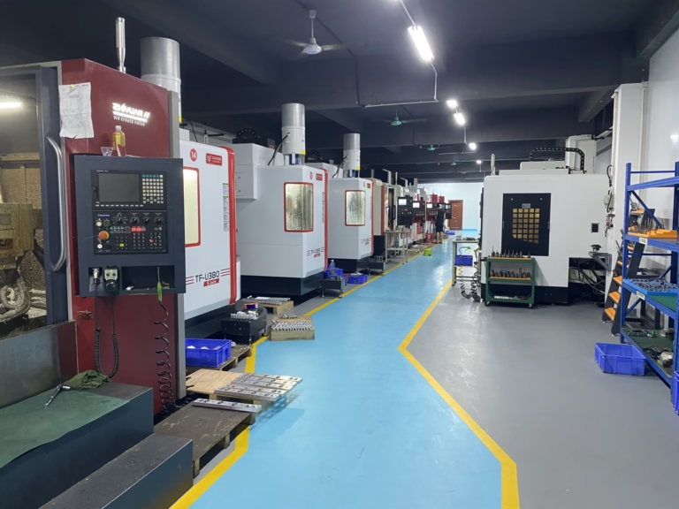
A shop with 12 four-axis mills and 16 five-axis centers can run the part in 3–5 days while you keep building.
Send the drawing, get a quote in 12 hours
Upload your part and we will return a quote with free DFM analysis. No minimum order quantity, from one prototype to 10,000+ parts.
12-hour quote100% inspection±0.005 mm toleranceNDA on request
More from the shop floor
We publish setup notes, tooling trials and inspection data from the factory floor.











