
How to Build CNC Plasma Cutting Machine: 7 Steps From Budget to First Cut
This guide walks engineers through building a 2-axis plasma table: cutting area, frame rigidity, drive selection, wiring, and post-processing of the kerf. It is written for people who already own or plan to buy a plasma power source and want to cut plate up to 12.7 mm. Read it and you can list your own parts, pick drives, and stress the weak points before cutting into the first 1,200 × 2,400 mm sheet.
In this article
- 1
- 2
- 3
- 4
- 5
- 6
- 7
- 8
Key takeaways
Define the cutting envelope before buying parts
Most failed builds start with a purchase, not a drawing. Before you buy rails or a gantry kit, write down three numbers: the largest sheet you must cut, the thickest plate, and the parts you expect to run each month. A shop cutting 3 mm signs once a week needs a very different machine than a shop cutting 12 mm brackets daily. The second machine needs mass and airflow; the first needs speed and a clean edge.
Cutting area drives everything else. A 1,200 × 2,400 mm sheet needs a frame around 1,500 × 2,700 mm once you add rail mounting, cable chain, and end stops. Pull the torch off the sheet at both ends and you still want 50 mm of travel margin. A 1,500 × 3,000 mm table is a common upgrade path for shops that want to run a full 4 × 8 ft sheet without repositioning.
Thickness sets the power source class. A 45 A machine cuts 6 mm steel cleanly at roughly 1,500 mm/min; 12 mm steel needs 65–85 A and drops to 600–800 mm/min. If your parts are mostly under 6 mm, a 45 A air plasma plus a water table will out-cut a bigger machine running slow. If you plan on 12 mm and up, budget for a 125 A class unit and a table that can hold a 200 kg sheet without sagging.
Finally, decide the machine's job. A plasma table is a 2D profiling machine. It will not hold ±0.05 mm on hole diameters; typical as-cut tolerance on 6 mm steel is ±0.5 mm, and holes smaller than the plate thickness come out tapered. If the drawing calls for a Ø10 H7 bore, plan to drill or ream after cutting. Design your workflow around that limit instead of fighting it.
- 1Cutting areaSheet size plus 150 mm per side for clamps, rails, and cable chain.
- 2Thickness range45 A for 6 mm, 65–85 A for 12 mm, 125 A for 25 mm.
- 3Tolerance target±0.5 mm on profiles, worse on small holes.
- 4Part mixSigns and art want speed; brackets and gussets want mass and airflow.
Frame, gantry, and drive choices that decide cut quality
A plasma torch does not push hard on the plate, but the machine still moves at 10–20 m/min with rapid direction changes. Any flex in the gantry shows up as a wavy edge, especially on thin sheet. Build the frame from 100 × 100 mm square tube with 4 mm wall or heavier, welded into a torsion box, then stress-relieve or at least let it sit before machining the rail mounting faces flat. A single unsupported 2,400 mm beam will bow under its own weight plus the gantry.
Rails and bearings set the practical accuracy. Round linear rails on supported shafts are cheap and forgiving for a first build. Profile rails (HG15 or HG20 class) hold preload better and resist the moment load from a cantilevered torch. On a 1,500 mm span, profile rails typically hold 0.05 mm over the length while unsupported round rail can drift past 0.2 mm once the gantry loads it. Mount both rails on the same machined plane, or shim until a dial indicator reads under 0.1 mm across the travel.
Drive choice is the most argued point in DIY plasma. Stepper motors with 3–5 N·m holding torque and a 10 mm pitch ball screw or a 3:1 belt reduction handle most hobby and light shop tables. Above 6 m/min on a 1,500 mm axis, steppers lose steps when the arc fires and the HF noise couples into the step signal. Closed-loop steppers or 400–750 W AC servos cost more but hold position under the same conditions. Servos also give you a real following error you can watch in the controller.
The Z axis matters more than most builders expect. Plasma needs a fixed torch height during the cut, usually 1.0–1.5 mm above the plate for steel, and a pierce height of 3–4 mm that drops to cut height after ignition. A Z axis with 100–150 mm travel and a floating head or ohmic sensor lets the controller find the plate and set height automatically. Without it, you will manually jog the torch and scrap parts when the plate warps.
- 1Frame stock100 × 100 × 4 mm square tube, torsion box, rails machined after welding.
- 2RailsProfile rail for 1,500 mm spans; supported round rail for short, light tables.
- 3MotorsStepper under 3 m/min, closed-loop or servo above 6 m/min.
- 4Z axis100–150 mm travel with ohmic or floating head sensing.
Wiring, grounding, and the plasma noise problem
Plasma cutting generates high-frequency start noise and a lot of it rides on the work lead, the torch lead, and the table itself. Treat the table as a grounded chassis: bond every frame section with a 6 mm² copper strap and drive a ground rod near the machine. The work clamp goes on the plate, not on the slats, and the lead should be as short as practical. Long work leads add resistance and noise.
Route signal cables away from the torch lead. Motor step and direction wires, limit switch wires, and the torch height control cable should run in a separate cable chain from the plasma lead, with a 150 mm minimum gap where they must cross. Shielded twisted pair cable grounded at the controller end only is standard practice. If you must run them together, use shielded cable on both and ground the shields at one point to avoid a ground loop.
Power the controller and the plasma from separate circuits if the shop allows. A 45 A plasma draws around 20 A at 230 V single phase; a 125 A unit can pull 60 A or more and will brown out a shared circuit on pierce. Put the controller on its own 10 A circuit and keep the plasma on a dedicated breaker sized to the nameplate. Add a line reactor or isolation transformer if the plasma is known to back-feed noise.
The torch height control (THC) is the part most DIY builds get wrong. Voltage-based THC reads arc voltage and adjusts Z to hold a steady standoff. The divider board inside the plasma must match the THC input range, usually 50:1 or 20:1. If the voltage reading jumps, the THC drives the torch into the plate or pulls it out of the cut. Set the THC delay to 0.5–1.0 s after pierce, and set the anti-dive so thin sheet does not trigger a false correction.
- 1Table ground6 mm² bonding straps on every frame section plus a local ground rod.
- 2Cable separationSignal and torch leads in separate chains, 150 mm gap at crossings.
- 3PowerDedicated breaker for the plasma; controller on its own 10 A circuit.
- 4THC setupMatch the divider ratio, delay 0.5–1.0 s, enable anti-dive on thin sheet.
Validate the machine before trusting it with a job
A new table is not ready because it moves. Run a three-test sequence before cutting customer parts. First, a dry run: jog the torch around the full cutting envelope at 50% rapid and listen for binding or a change in motor pitch. Second, a straight-line cut: cut a 500 mm line in 6 mm steel, flip the part, and measure the kerf on both faces. A tapered kerf wider than 0.3 mm across the thickness means the torch is not perpendicular or the standoff is wrong.
Third, a dimensional coupon. Cut a 100 × 100 mm square with a 20 mm center hole, then measure the outside with calipers and the hole with a pin gauge. Profile error should be under ±0.5 mm on 6 mm steel. If the square is parallelogram-shaped, the gantry is out of square. If the hole is oval, check backlash on both axes. If the corner is rounded, the acceleration is set too low or the THC is diving at the corner.
Record the settings that worked. Plasma cutting is sensitive to consumable wear, and a nozzle that has cut 300 pierces will need a different cut height than a new one. Keep a log of amperage, cut speed, pierce delay, and consumable hours for each material thickness. A shop that tracks this cuts scrap rates by half compared with one that tunes by ear.
Watch consumables. A worn electrode shows a rounded tip and a wider kerf; a worn nozzle shows an oval orifice and a beveled cut. Replace both as a set. On a 45 A air plasma cutting 6 mm steel, expect roughly 600–1,000 pierces per electrode set, and less if you cut a lot of stainless or aluminum.
- 1Dry runFull envelope at 50% rapid, listen for binding.
- 2Kerf checkCut 500 mm, measure both faces, taper under 0.3 mm.
- 3Dimensional coupon100 mm square and 20 mm hole, profile error under ±0.5 mm.
- 4Consumable logTrack pierce count per electrode set to predict edge quality loss.
When building in-house stops making sense
A DIY plasma table makes sense when the parts are flat, the tolerance is loose, and the volume is low to moderate. Signs, gussets, mounting plates, and weld-prep blanks fit this profile. The build also teaches your team how the machine behaves, which helps when you later buy a production unit. Budget the project honestly: frame, rails, drives, controller, THC, plasma source, water table, and ventilation add up fast, and the labor is usually more than the parts.
Building stops making sense when the parts need tight tolerance, a good surface finish, or 3D features. Plasma leaves a heat-affected zone, a beveled edge, and a rough cut face. If the drawing calls for ±0.05 mm, Ra 0.8–1.6 μm, or a threaded bore, the part needs machining after cutting. That is the point where many shops send the profile out and keep the finishing in-house, or skip plasma and start from plate.
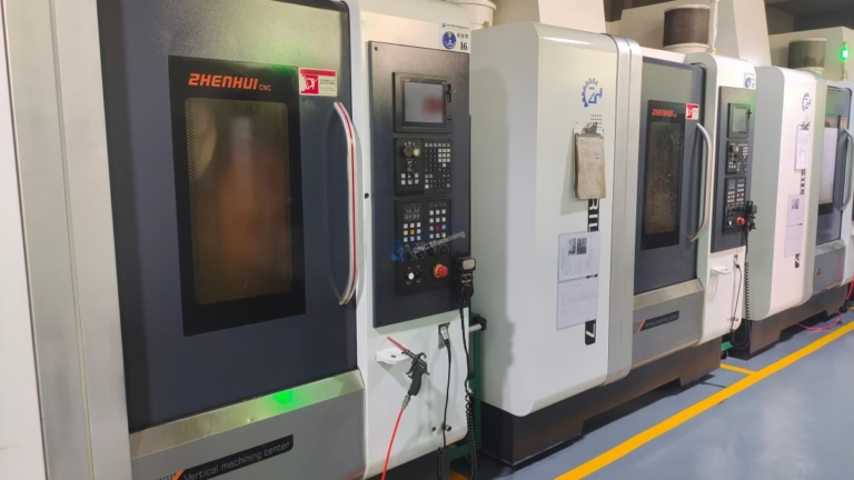
At GreatLight we run 127 high-precision CNC machines across three plants, including 16 simultaneous 5-axis machining centers and a 4,000 mm maximum processing size. We machine aluminum, stainless, steel, copper, titanium, and engineering plastics to ±0.005 mm, with 100% inspection before shipment. If your flat part needs a finished bore, a faced flange, or a tight slot after plasma cutting, that is the step we handle. Quotation and free DFM analysis come back within 12 hours, and production can start within 24 hours.
The practical split is simple. Cut flat profiles on your own table if the edge meets the drawing. Send the part to a machine shop when the drawing calls for tolerance the torch cannot hold. Mixing the two keeps the plasma table busy with the work it does well and avoids scrapping parts that needed a milling step first.
- 1Keep in-houseFlat profiles, weld prep, signs, gussets, loose tolerance.
- 2Send out±0.05 mm fits, bores, threads, Ra 0.8–1.6 μm faces.
- 3Hybrid workflowPlasma the blank, machine the critical features.
- 4Quote turnaround12 hours with free DFM, production start in 24 hours.
Step by step: from frame to first cut
Follow the order. Skipping the alignment step is the most common reason a new table cuts tapered parts.
- 11. Set the frame and level itWeld the torsion box, then level the frame to within 1 mm across the diagonals. A 1,500 × 3,000 mm frame should read the same diagonal measurement within 1.5 mm. Shim the feet, do not bend the frame. Let the weld cool fully before measuring.
- 22. Machine or shim the rail mounting facesIf you have access to a mill, face the rail pads flat. Otherwise shim with 0.05 mm stainless shim stock until a dial indicator reads under 0.1 mm over the full travel. Parallelism between the two X rails controls how square your parts come out.
- 33. Mount rails, gantry, and driveTorque rail bolts to the rail maker's spec, usually 15–20 N·m for M5. Set belt tension so a 500 mm span deflects 5–8 mm under light thumb pressure. Check backlash at the motor coupling: aim for under 0.05 mm at the torch.
- 44. Square the gantry to the railsClamp a dial indicator to the gantry and sweep a machined square or a 1,200 mm straight edge. Adjust the gantry until the X and Y axes are square within 0.1 mm over 1,000 mm. This step sets the accuracy of every part you cut.
- 55. Install the Z axis and torch mountSet the torch perpendicular to the plate within 0.5°. A 2° tilt on 6 mm steel shows up as a visibly beveled edge. Mount the torch so the tip is the lowest point of the assembly, or you will crash the nozzle on a tip-up.
- 66. Wire, ground, and set travel limitsBond the frame, run shielded signal cable, and set soft limits 20 mm inside the hard stops. Jog each axis at 25% speed and watch for cable chain binding. Set the home switches so homing does not drive the gantry into the frame.
- 77. Configure CAM and cut a test couponEnter the real kerf, typically 1.5 mm at 45 A on 3 mm steel and 2.5–3.0 mm at 85 A on 12 mm. Set pierce height 3–4 mm and cut height 1.0–1.5 mm. Cut a 100 × 100 mm square with a 20 mm hole and measure it before running a real job.
Component choices by build level
Use this to sanity-check a parts list. Numbers are typical ranges for air plasma on mild steel.
| Build level | Drive | Rail type | Cut speed | Best for |
|---|---|---|---|---|
| Hobby 1,200 mm | NEMA 23 stepper, 3 N·m | Supported round rail | 2–4 m/min | Signs, art, 3–6 mm sheet |
| Light shop 1,500 mm | Closed-loop stepper | Profile rail HG15 | 6–10 m/min | Brackets, gussets, 6–10 mm |
| Production 3,000 mm | 750 W AC servo | Profile rail HG20 | 12–20 m/min | 12 mm plate, daily runs |
| Heavy plate 3,000 mm | 1 kW AC servo | Profile rail HG25 | 6–10 m/min | 16–25 mm plate, high duty |
Build the table for flat work. Machine the tight features.
A well-built plasma table is a profiling machine, not a precision machine. Keep it on flat parts with loose tolerance, and send the bores, threads, and finished faces to a CNC shop. That split keeps scrap low and the table productive.
Frequently asked questions
What is the minimum budget to build a CNC plasma cutting machine?
A hobby-grade 1,200 × 1,200 mm table with a 45 A air plasma, stepper drives, and a basic THC typically lands in the low thousands of US dollars when you source used or import parts. The plasma source and the THC are the two items where cheap parts cost the most in scrap later.
Can I use any plasma cutter for a CNC build?
No. The machine needs a CNC interface, usually a torch on/off relay and a divided arc voltage output. Many hand-held plasma units have neither. Check for a CNC port or a machine torch option before buying.
Air quality also matters. Moisture in the air supply causes erratic arc starts and short consumable life. Add a refrigerated dryer and a coalescing filter before the plasma inlet.
How important is frame rigidity for a CNC plasma cutter?
It is the single biggest factor in cut quality. A flexible gantry changes torch standoff during acceleration, which changes arc voltage and cut width. A stiff torsion-box frame holds standoff steady and lets the THC do its job.
Mass helps, but stiffness matters more. A heavy frame that twists under load is worse than a lighter frame that does not.
What software do I need to control a CNC plasma cutter?
Three layers: CAD for the drawing, CAM for the toolpath and kerf compensation, and a controller that turns G-code into motion. Fusion 360, Inkscape, and SheetCam are common on DIY builds. LinuxCNC, Mach3, and Masso are common controllers.
Set the kerf in CAM to the real number you measured on a test coupon. A default kerf that does not match your machine will make every part oversized.
What safety precautions apply when building and running a plasma table?
Plasma cutting produces intense UV, fumes, and high voltage. Use a water table or downdraft to control smoke, and wear flame-resistant gloves, a face shield, and a respirator rated for metal fume. Enclose the table so nobody looks at the arc without eye protection.
Electrically, ground the table, keep the work clamp on the plate, and never open the plasma case while it is powered. The start circuit holds a dangerous charge even after shutdown.
Can GreatLight help if I do not want to build from scratch?
Yes. We machine flat and 3D parts from plate and bar, including the finishing steps a plasma table cannot hold. With 127 CNC machines and a 4,000 mm maximum processing size, we cover prototypes through 10,000+ part runs with no minimum order quantity.
Upload a drawing for a quotation and free DFM analysis within 12 hours. Files stay confidential, and an NDA is available on request.
Need the machined features after the cut?
Send your drawing and we will quote the finishing step, with a free DFM analysis and a reply within 12 hours.
12-hour quote100% inspectionNo minimum orderNDA on request
More from GreatLight
We publish setup notes, tooling trials and inspection data from the factory floor.











