
How to Ground a CNC Machine
Grounding is not one wire to a rod. A spindle, servo drives and a VMC frame all need a low-impedance path back to earth, and the target is usually 10 Ω or less. This guide is for maintenance techs and shop engineers who have to sign off the installation. You will get the resistance targets, the conductor sizes and the mistakes that cause random alarms.
In this article
- 1
- 2
- 3
- 4
- 5
- 6
- 7
- 8
- 9
Key takeaways
Why a CNC machine needs more than one ground path
A CNC machine has two ground jobs and they get confused constantly. The safety ground protects the operator. If a live conductor touches the frame, fault current has to return fast enough to trip the breaker. That path runs from the frame through the bonding conductor to the building earth bar.
The second job is noise. Servo drives switch at 4 kHz to 16 kHz. That switching pushes high-frequency current onto the frame and the cable shields. If the impedance to earth is high, the noise rides on the encoder and scale signals instead. You see it as random following errors, not as a shock.
Both jobs use the same earth bar but not the same conductor. A 16 mm² copper safety conductor carries fault current. A separate 4–6 mm² signal conductor carries shield and control noise. Tie them at one point, at the earth bar. Nowhere else.
- 1Safety groundFrame, door, panel and motor bodies. Sized for fault current.
- 2Signal groundCable shields, 0 V reference, scale earth. One point only.
- 3Common mistakeBonding the shield at both ends. That makes a loop antenna.
Check the building earth before you touch the machine
Start at the panel, not at the machine. Measure the resistance from the earth bar to a known good reference. If the building earth is already above 10 Ω, no amount of work at the machine will fix it. Fix the electrode first.
Look at how other machines are bonded. In older shops you often find three machines landed on one lug with a jumper. That is a daisy chain. A fault in one machine raises the frame potential of the other two, and the noise path is shared.
Ask for the soil condition. Dry sand and rock read far higher than damp clay. In a dry season the same rod can drift from 8 Ω to 30 Ω. If the site is sandy, plan for two rods spaced at least 3 m apart rather than one deep rod.
Pick the conductor size from the machine rating
Size the safety conductor from the supply breaker, not from the spindle power. A 32 A feed needs at least 6 mm² copper. A 63 A feed needs 16 mm². A 100 A feed needs 25 mm². These are minimums; going one size up costs little and lowers impedance.
Use stranded copper, not solid. Stranded cable tolerates the vibration that a machine tool makes all day. Solid core work-hardens at a terminal and cracks after a few years.
Keep the run short and direct. Every extra metre adds impedance. If the earth bar is 20 m away, run the conductor in a straight route rather than coiling the spare length inside the cabinet. A coil of spare cable is an inductor, and it blocks the high-frequency noise you are trying to drain.
Bond the frame, spindle and panel as one body
Paint and anodizing are insulators. The machine frame may look like one casting, but the door, the panel gland plate and the spindle housing are often isolated by coating. Measure from the spindle housing to the main frame with a milliohm meter. Anything above 0.1 Ω needs a bonding strap.
Use braided copper straps, not round wire, for moving parts. A flat braid of 25 mm × 3 mm carries the same current as a much thicker round conductor and survives millions of flex cycles.
Bond the control cabinet to the machine frame with a short, wide strap. Keep it under 300 mm if you can. Long thin bonds have enough inductance to let drive noise sit on the cabinet and radiate into the encoder cables.
- 1Scrape to bare metalRemove paint under every lug, then re-seal with anti-corrosion paste.
- 2Star washers both sidesThey bite through oxide and hold torque under vibration.
- 3Torque the lugM8 lugs at 15–20 N·m, M6 at 8–10 N·m.
What to measure and what the numbers mean
Earth resistance is the headline number. Below 5 Ω is excellent, 5–10 Ω is normal in a good shop, and 10–25 Ω is acceptable only if the cable run is short. Above 25 Ω, fix the electrode or the soil before you blame the machine.
Frame continuity between bonded parts should sit under 0.1 Ω. This is a milliohm measurement, so use a four-wire meter. A two-wire multimeter lead resistance alone can read 0.3 Ω and hide a real problem.
Earth leakage current under normal running should be a few milliamps. Drive filters and switching supplies put a small current on the frame by design. If it climbs past 30 mA, disconnect drives one at a time and find the source. Do not simply lift the safety conductor to make the reading go away.
Six grounding mistakes that cause intermittent faults
The first is using the building steel as the only earth. Structural steel is bonded for lightning, not for drive noise, and its impedance at 10 kHz is far higher than at 50 Hz. Run a dedicated copper conductor.
The second is bonding a cable shield at both ends. That turns the shield into a loop that picks up every drive in the shop. Bond at the cabinet, insulate at the motor, and the noise drains one way.
The third is sharing an earth conductor between machines. When one machine faults, the other sees a voltage rise on its frame. It also couples drive noise between machines that have nothing to do with each other.
The fourth is a loose lug. Thermal cycling loosens terminals over a few months. Re-torque the earth lugs at the first scheduled service and every year after that.
The fifth is painting over the bonding point. A lug on a painted frame reads open at high frequency even though a DC meter shows continuity. Scrape to bare metal and use a star washer.
The sixth is disconnecting the safety earth to chase noise. Never do it. Fix the shield, the bond or the cable routing instead. Lifting the earth makes the machine unsafe and usually does not solve the alarm.
Step by step: how to ground a CNC machine
- 11. Lock out and verify deadOpen the main breaker, apply a lock, and test L1, L2, L3 and N to earth. Expect below 5 V. Anything higher means a backfeed from another panel or a UPS.
- 22. Locate the machine earth lugIt is a stud or lug near the power entry, usually marked PE or with the earth symbol. Do not use a mounting bolt on the base casting instead. Check the manual if it is not obvious.
- 33. Measure the existing earth resistanceUse a three-pole or clamp earth tester at the building bar. Write the number down. If it is above 10 Ω, add a rod or improve the connection before continuing.
- 44. Run the safety conductor6 mm² copper for a 32 A feed, 16 mm² for 63 A, 25 mm² for 100 A. Crimp a ring lug, scrape the paint, and torque to the value in the manual. Route it away from drive cables.
- 55. Run the signal conductor separately4–6 mm² from the control earth terminal to the same earth bar. Bond cable shields at the cabinet end only. Leave the far end open and insulated.
- 66. Bond every isolated panelDoor, gland plate, spindle housing, and the operator station. Use 25 mm × 3 mm braid for anything that moves. Target below 0.1 Ω between parts.
- 77. Test before power-upContinuity from the farthest frame point back to the earth bar. Expect below 0.1 Ω. Insulation resistance from L1, L2, L3 and N to earth at 500 V DC. Expect above 1 MΩ.
- 88. Re-check under powerPower up and run a spindle ramp to 8,000 rpm. Measure earth current with a clamp meter. A few milliamps is normal. Above 30 mA points to a filter or drive fault, not to the grounding.
Grounding targets by measurement
Use these values for a typical VMC or turning center on a 400 V supply.
| Measurement | Good | Investigate | Fix first |
|---|---|---|---|
| Earth resistance at bar | ≤ 5 Ω | 5–10 Ω | Above 25 Ω |
| Frame-to-bar continuity | ≤ 0.1 Ω | 0.1–0.3 Ω | Above 0.3 Ω |
| Bonded panel to frame | ≤ 0.1 Ω | 0.1–0.5 Ω | Above 0.5 Ω |
| Earth leakage running | ≤ 10 mA | 10–30 mA | Above 30 mA |
| Insulation L to earth | > 100 MΩ | 10–100 MΩ | Below 1 MΩ |
| Shield bond points | One end only | — | Both ends |
Ground it once, test it twice
A dedicated copper conductor, one bonding point and a resistance check before power-up solve most random drive alarms. If the building earth is above 25 Ω, fix that first.
Grounding questions we get from the shop floor
Can I use one earth rod for several CNC machines?
You can share the electrode, but each machine needs its own conductor back to the earth bar. Do not jumper from one machine lug to the next. That is a daisy chain and it couples fault current and drive noise between machines.
What resistance should a grounding rod read?
A single copper-clad steel rod driven 2.4 m (8 ft) into damp clay often reads 5–15 Ω. Dry sand can read over 50 Ω with the same rod. If you are above 25 Ω, add a second rod at least 3 m away and bond the two.
Should the control 0 V be connected to earth?
Follow the builder. Many CNC controls float the 0 V and bond the shield, not the supply. If you tie 0 V to earth at both the cabinet and the machine frame, you create a loop that shows up as following error at high feed rates.
Why do my alarms stop when I disconnect the earth?
That is a symptom, not a fix. Lifting the earth changes the noise path, so the alarm moves elsewhere or goes quiet for a while. The real cause is usually a shield bonded at both ends or a high-impedance bond on a painted panel.
How often should I re-test the machine ground?
Test at installation, then at each annual service. Re-torque the earth lugs at the same time. Machines in a humid or oily shop can corrode a lug in under a year, and corrosion raises resistance quickly.
Does the machine need its own earth rod?
Not usually. A dedicated conductor back to the building earth bar is the normal arrangement and it is easier to test. A separate rod is only needed when the building earth is poor or the run is very long.
Parts machined on a properly grounded machine
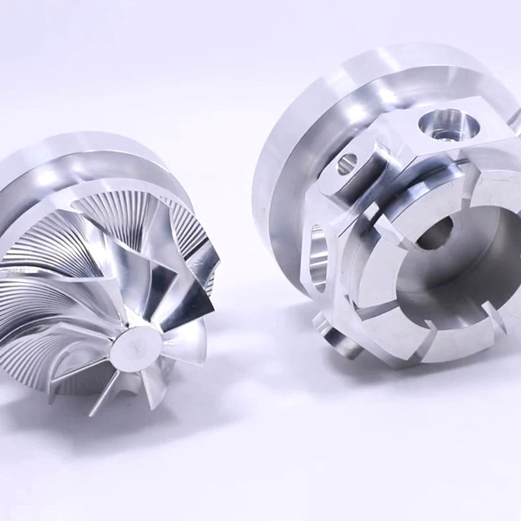
Tolerances of ±0.005 mm and Ra 0.8–1.6 μm hold better when the drives are quiet. Upload a drawing and we reply with a quote and DFM notes within 12 hours.
12-hour quote100% inspection±0.005 mm
More from the shop floor
We publish setup notes, tooling trials and inspection data from the factory floor.











