
How to Measure Depth Accuracy on a CNC Machined Object
Depth is the hardest feature to measure because it depends on a datum that is usually not the face you just cut. This guide shows how we set a datum, pick a gauge, and confirm depth on a CNC machined object to ±0.005 mm. It is written for engineers and incoming-inspection teams who need a number they can defend.
In this article
- 1
- 2
- 3
- 4
- 5
- 6
- 7
Key takeaways
What measure depth accuracy really means on a CNC machined object
A depth callout is a distance between two surfaces. One of them is the datum the drawing names; the other is the floor of a pocket, slot, counterbore or step. If you measure from the top face of the part instead of the datum, you are checking a different dimension. On a clean part the two numbers often agree within 0.01 mm, which is exactly why the mistake survives for months before a functional failure exposes it.
Depth error rarely comes from the tool alone. Thermal growth in the spindle and part, chip packing in a blind pocket, tool push-off on a long reach, and fixture lift all move the floor. A 6 mm carbide end mill at 3 × D reach can deflect 0.02 mm under normal finishing loads. Measuring accuracy is how you find out whether the floor moved or the gauge lied.
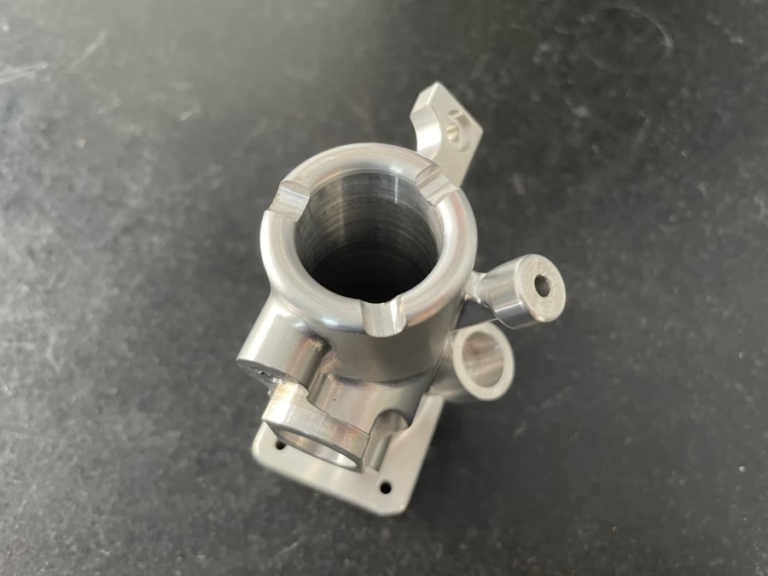
The tolerance band decides the method. A ±0.1 mm depth on a bracket can be checked with a caliper and a straightedge. A ±0.005 mm bore depth in an aluminum manifold needs a depth micrometer or a CMM with a calibrated stylus, and it needs the part to sit at 20 °C first. Gauge resolution should be about one tenth of the tolerance band.
Before you trust any number, ask three questions. What is the datum? What is the gauge uncertainty? What was the part temperature? If the inspection report does not answer all three, the depth value is an opinion.
- 1Datum firstRead the drawing frame before you touch the part.
- 2ResolutionTarget gauge resolution of one tenth of the tolerance band.
- 3Thermal soakLet the part sit at 20 °C for 30–60 minutes before final checks.
Set the datum and clamp before you measure depth
Start by cleaning the part. Chips in a blind pocket add 0.05–0.2 mm of false depth, which is larger than most of the tolerances we hold. Blow out the feature with dry air at 0.4–0.6 MPa, then wipe the datum face with a lint-free cloth. Never measure a part straight off the machine while coolant is still pooled in the pocket.
Mount the part the same way for every reading. For a height gauge, rest the datum face on a granite plate and check that the part does not rock. For a depth micrometer, keep the gauge axis perpendicular to the floor within 2–3°. A 5° tilt on a 20 mm depth reads about 0.08 mm long. That single error can consume an entire tolerance band.
On a CMM, define the datum plane with at least four points spread across the face, not three points clustered in one corner. Probe the pocket floor with five to nine points and report the minimum and maximum, not only the average. A dished floor from a worn tool shows up in the spread long before it shows up in the mean.
Record the setup. Fixture, stylus number, probe force and orientation belong in the inspection record. If a second operator repeats the check and gets a different number, the setup, not the part, is usually what changed.
- 1Dry air, then wipeBlow out blind features at 0.4–0.6 MPa before gauging.
- 2Perpendicular within 2–3°A tilted depth micrometer reads long by roughly 0.4% of depth per degree.
- 3Spread beats averageMin and max points reveal floor dishing that a mean hides.
Choose the gauge that matches the feature
A depth micrometer is the default for shallow features from about 0.5 mm to 25 mm deep. Use the rod that covers the range with the least extension, because every extension adds stack-up error. Check zero on a flat gauge block before and after the run. Rods wear at the tip, and a worn rod reads short by 0.005–0.01 mm.
Gauge pins plus a height gauge work well for slots and step depths where the floor is narrow. Drop a pin that fits the slot with 0.01–0.02 mm clearance, measure over the pin, then subtract the pin diameter. This method fails on tapered slots, because the pin sits at whatever height the taper allows.
For deep bores over 25 mm, use a bore gauge with a depth stop or a CMM. A vernier caliper depth rod is not a precision instrument at this scale. Its blade flexes under thumb pressure, and the reading changes by 0.03–0.05 mm depending on how hard you push. Use it for rough checks only.
Optical and laser methods suit soft materials, thin walls and features you cannot touch without marking. They need a calibrated reference step in the same field of view. Without that reference, a laser depth reading drifts with surface finish, and a mirror-polished floor will read differently from a machined one.
- 1Depth micrometerBest from 0.5 mm to 25 mm; verify zero on a gauge block.
- 2Pin and height gaugeGood for narrow slots; avoid on tapered walls.
- 3CMM or bore gaugeUse beyond 25 mm depth or where you need point data.
Control temperature before you record depth accuracy
Steel expands about 11.5 μm per meter per °C; aluminum about 23 μm. A 100 mm aluminum part that is 5 °C warmer than the gauge reads roughly 0.011 mm long in every direction, including depth. That is twice the ±0.005 mm tolerance we hold on many features. Let the part and the gauge sit in the same room for 30–60 minutes before final inspection.
The gauge matters as much as the part. A steel micrometer and an aluminum part reach equilibrium at different rates. If you bring a part in from a cold truck in winter, the surface warms fast and the core stays cold for over an hour. Check a scrap part of the same material and section first.
Air currents from a doorway or a fan create a gradient across a 300 mm part. Keep the inspection area away from open doors, and use a granite plate rather than a steel bench. Granite has lower thermal conductivity, so it holds temperature and does not pull heat out of the part.
Log the room temperature with the reading. If the shop runs at 25 °C and the drawing assumes 20 °C, correct the number or state the condition in the report. An uncorrected depth value at a 5 °C offset is a documented nonconformance waiting to happen.
- 1Soak 30–60 minutesPart and gauge must reach the same temperature.
- 2Granite over steelLower conductivity keeps the plate from chilling the part.
- 3Correct or stateEither apply the expansion factor or record the room temperature.
Step by step: how to measure depth accuracy
Follow this order on every part. Skipping a step usually shows up as a 0.01–0.05 mm error.
- 11. Read the datum from the drawingIdentify which face the depth is measured from. Highlight it on the print and mark it on the part with a paint pen. Do not assume the top face is the datum.
- 22. Clean the feature and the datumBlow out chips at 0.4–0.6 MPa, then wipe with a lint-free cloth. Check the pocket floor with a light and a mirror if the feature is deep.
- 33. Let the part soakPlace the part and the gauge on the granite plate for 30–60 minutes. Confirm both are within 1 °C of each other with a contact thermometer.
- 44. Zero the gaugeCheck a depth micrometer against a gauge block at the low end of its range. Record the zero error and apply it to every reading.
- 55. Take at least three readingsProbe the floor at three to five points spread across the feature. Keep the gauge axis perpendicular within 2–3°. Record min, max and mean.
- 66. Compare against the tolerance bandSubtract the gauge uncertainty from the usable band before you judge the part. A ±0.005 mm callout with a 0.002 mm gauge leaves 0.003 mm of real margin.
- 77. Log the result and the conditionsWrite down the gauge ID, stylus, room temperature and setup. A number without its conditions cannot be repeated.
Gauge selection by depth and tolerance
Pick the method from the tolerance band first, then from the feature depth.
| Method | Typical range | Best for | Watch out for |
|---|---|---|---|
| Depth micrometer | 0.5–25 mm | Shallow pockets and counterbores | Rod tip wear reads 0.005–0.01 mm short |
| Pin plus height gauge | 1–50 mm | Narrow slots and steps | Tapered walls seat the pin high |
| Bore gauge with stop | 25–150 mm | Deep bores and cylinder depth | Stop face must sit flat on the datum |
| CMM with stylus | 0.5–500 mm | Complex geometry and point data | Probe force deflects thin floors |
| Vernier caliper rod | 0.5–150 mm | Rough checks only | Blade flex adds 0.03–0.05 mm |
| Optical or laser | 0.1–100 mm | Soft parts and thin walls | Needs a calibrated reference step in view |
Frequently asked questions
Can I measure depth with a caliper if the tolerance is loose?
Yes, if the tolerance band is wider than about ±0.05 mm and the feature is easy to reach. Push lightly and take three readings, because the blade flexes under thumb pressure.
For anything tighter than ±0.05 mm, move to a depth micrometer or a CMM. A caliper is a shop-floor check, not an inspection result.
Why does my depth reading change between operators?
The setup changed, not the part. Clamp position, gauge tilt and probe force all shift the number. A 5° tilt on a 20 mm depth reads about 0.08 mm long.
Write the setup into the inspection plan: fixture, stylus, orientation and gauge ID. Then two operators should land within the gauge uncertainty of each other.
How many points should I probe on a pocket floor?
Three points catch a tilt, five to nine catch dishing from a worn tool. Spread them across the whole floor, not in one corner.
Report the minimum and maximum. If the spread is larger than a third of the tolerance band, stop and check the tool and the program before you accept the part.
Does surface finish affect depth measurement?
It does on laser and optical methods. A mirror-polished floor reflects differently from an as-machined one, and the reading shifts with the finish.
Contact methods are less sensitive, but a rough floor still adds uncertainty. On a Ra 1.6–3.2 μm floor, expect 0.002–0.005 mm of scatter at the contact point.
When should depth be checked on a CMM instead of by hand?
Use a CMM when the datum is a compound surface, when the feature is under 1 mm wide, or when you need point data to see floor shape. It also helps when the part cannot be clamped on a plate.
For a simple counterbore at ±0.05 mm, a depth micrometer is faster and just as good. Match the method to the callout.
What uncertainty should I quote on a depth report?
Quote the gauge error plus the temperature effect plus your repeatability from three readings. On a depth micrometer at 20 °C, that is often 0.003–0.005 mm.
Subtract that uncertainty from the tolerance band before judging the part. If nothing is left, the measurement method is not capable for that callout.
Send us the drawing and the depth callout
We quote in 12 hours with a free DFM review, machine to ±0.005 mm, and inspect 100% of parts before shipment. Tell us what the datum is and we will tell you how we hold it.
12-hour quote±0.005 mm tolerance100% inspection
More from the shop floor
We publish setup notes, tooling trials and inspection data from the factory floor.











