
How to Quiet a CNC Machine
This guide is for machinists, maintenance techs and shop managers who need to bring a CNC machine down to a workable sound level. It walks through where the noise actually comes from, which fixes change the reading on a sound meter, and which ones only move the problem around.
In this article
- 1
- 2
- 3
- 4
- 5
- 6
- 7
Key takeaways
Where CNC noise actually comes from
Before buying anything, split the noise into three parts: the source, the path and the receiver. The source is the cutting zone, the spindle, the pumps and the chip conveyor. The path is everything the vibration travels through, which in most shops means the machine base, the sheet metal enclosure, the floor slab and the building frame. The receiver is the operator standing at the door. Most shops attack the source, find the machine is still loud, and stop there.
The cutting zone dominates on non-ferrous work. Aluminum cuts at 8,000 to 18,000 rpm on small tools, and the resulting tone sits high in the spectrum, around 2 to 8 kHz, where human hearing is most sensitive. Steel and cast iron cut slower but the interrupted edges of a face mill put energy into the 200 to 800 Hz band, which travels through the frame and shakes the panels.
A worn or unbalanced tool raises the level across the whole spectrum. A single chipped insert on a 63 mm face mill can add 6 to 10 dB(A) at 1 m, because the chip load on one tooth is now different from the others. That is a detectable change on any handheld meter and it is free to fix.
Coolant and air also contribute. High-pressure coolant at 70 bar hitting a rotating tool generates broadband noise near the nozzle. Shop air blowing chips off a vise can exceed 90 dB(A) at close range. Neither is the cutting process, but both end up in the same reading.
- 1Cutting zoneTool condition, speeds, feeds, radial engagement, workpiece material.
- 2Machine systemsSpindle bearings, way covers, pumps, chip conveyor, hydraulics.
- 3StructureEnclosure panels, base casting, floor slab, nearby steelwork.
Fix the cutting process before you add panels
Start with the tool. Check runout on every holder with a dial indicator at the gauge line: 0.010 mm TIR is a reasonable target for a finish tool and 0.020 mm for roughing. Above 0.030 mm you will hear a beat frequency as the tool rotates, and no enclosure will hide it. Balance holders above 10,000 rpm. A balanced holder at 15,000 rpm removes a tone that operators describe as a whistle.
Then look at the cut. Increase radial engagement and reduce the number of passes where the machine allows it, because fewer, deeper cuts excite the structure less often. On aluminum, a 12 mm carbide end mill at 12,000 rpm with a 0.08 mm feed per tooth and 40 percent radial engagement is a smoother cut than a 6 mm tool at 20,000 rpm with 10 percent engagement. The second one sounds sharper because it is.
Climb milling on a rigid machine produces a more even chip load than conventional milling, which lowers the impulse at each tooth entry. If the part rings, add a support under the unsupported span before changing the program. A single jack screw under a thin plate can drop the reading by several dB(A) because the plate cannot flex and radiate.
Watch the spindle load meter during the cut. A load that swings more than 15 percent within one pass means the chip load is varying, and the sound you hear is that variation. Smoothing the load is usually a CAM or fixture fix, not an acoustic one.
- 1Runout target0.010 mm TIR for finish tools, 0.020 mm for roughing.
- 2BalanceBalance holders above 10,000 rpm; rebalance after any insert change.
- 3EngagementFewer deep passes usually run quieter than many shallow ones.
Stop the machine structure from acting as a speaker
The enclosure is a large thin steel box with a lot of surface area, and surface area is what radiates sound. Panels that are free to flex at 100 to 400 Hz will do exactly that. Adding mass is the most predictable fix: a damping sheet bonded to the inside face of each side panel typically cuts the radiated level by 3 to 6 dB(A) in the low mid band. The sheet needs full contact, not spot adhesive, or it will rattle.
Check the doors and covers. A door that closes with a loose latch buzzes at one tone and disappears at another. Adjust the latch, replace worn gaskets, and tighten any panel screw that has backed out. Walk around the machine with the spindle running at 6,000 rpm and no cut: if you hear a panel, you have found a free fix.
The floor matters more than most people expect. A machine standing on a thin suspended slab will transmit vibration into the building, and the slab radiates it back. Isolating pads under the leveling feet reduce transmission, but they must match the machine weight. A pad rated for 500 kg under a 1,200 kg corner will flatten and do nothing. Level the machine first, then torque the feet.
If the shop has hard parallel walls and a low ceiling, the room itself adds to the level at the operator position. Absorptive panels on one wall and part of the ceiling reduce the reverberant field. This does not lower the machine output, but it lowers what the operator experiences, which is often the actual goal.
- 1Panel dampingFull-contact damping sheet inside enclosure panels, 3 to 6 dB(A) typical.
- 2Hardware checkLatches, gaskets and loose screws cause tonal buzzes.
- 3Isolation padsMatch the load rating to the actual corner weight.
What the operator hears, and what the rules allow
Noise exposure limits vary by region, but the engineering logic is the same: reduce the level at the ear, limit time at the loudest jobs, and provide protection where the other two are not enough. A machine that reads 85 dB(A) at the door on a roughing job will exceed 90 dB(A) inside the enclosure during a deep cut. If an operator has to stand at the door to watch the tool, that position is the one to treat.
Log the numbers. Take a reading at the operator position with the machine cutting the normal production part, not a test block. Repeat for the three loudest jobs in the cell. This gives you a baseline and tells you whether a change helped. Without it, every fix is a guess and every argument about cost has no data behind it.
In many shops the largest single reduction comes from moving the roughing work to a machine that is already isolated or in a separate bay, and keeping the quiet finishing work on the machines near the walkways. That is a scheduling decision and it costs nothing. It also keeps operators out of the highest-exposure jobs for long stretches.
If you also buy machined parts and noise is a problem in your own assembly area, the geometry and finish of the parts matter. Thin unsupported walls ring; adding a rib or a boss costs a little machining time and removes a source of noise downstream. We see this often on covers and brackets.
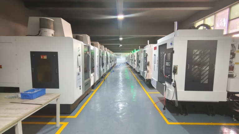
At GreatLight we run 127 high-precision CNC machines across 3 wholly-owned plants, with 16 simultaneous 5-axis machining centers. When a customer sends a part that rings in service, we can check wall thickness, rib placement and surface finish and quote a revised geometry. Quotation and free DFM analysis come back within 12 hours.
- 1Baseline readingMeasure on the real production job, at the operator position.
- 2SchedulingMove the loudest roughing to an isolated bay where possible.
- 3Part designRibs and adequate wall thickness cut ringing downstream.
Step by step: quieting a CNC machine
Work from the cheapest and most reversible change to the most expensive. Do not skip a step because it looks too simple.
- 11. Take a baseline readingUse a Class 2 sound level meter on the A-weighted, slow setting. Measure at the operator position and at 1 m from the enclosure, on the three loudest production jobs. Write down the machine state, spindle speed and tool. This is your reference for every later change.
- 22. Check tool runout and balanceIndicate every holder at the gauge line. Target 0.010 mm TIR for finishing and 0.020 mm for roughing. Balance holders used above 10,000 rpm. Replace any insert with a chipped edge before it goes back in the spindle.
- 33. Adjust the cut, not the enclosureReduce the number of passes, raise radial engagement where the setup allows, and keep spindle load variation within about 15 percent per pass. On aluminum, 12,000 rpm with 0.08 mm per tooth often runs quieter than 20,000 rpm with a lighter chip.
- 44. Support the workpieceAdd jacks, clamps or a fixture support under any unsupported span. A thin plate that can flex will radiate. Check the fixture bolts for tightness: a loose T-nut buzzes at a specific tone and disappears at another.
- 55. Tighten and damp the enclosureWith the spindle running at 6,000 rpm and no cut, walk around the machine and press on each panel. Anything that changes tone when you press it needs a screw, a gasket or a damping sheet. Bond damping sheet with full contact to the inside face.
- 66. Isolate the machine from the floorLevel the machine first, then fit isolation pads rated for the actual corner load. A pad rated for 500 kg under a 1,200 kg corner will flatten. Re-check level after 24 hours of running.
- 77. Treat the room and the scheduleAdd absorptive panels on one wall or part of the ceiling if the operator position is in a reverberant corner. Move the loudest roughing jobs to an isolated bay or to a machine away from walkways. Re-measure the same three jobs and compare with the baseline.
Which fix gives what, and when to skip it
Expected reductions are typical for a vertical machining center cutting aluminum or steel. Actual results depend on the machine and the job.
| Fix | Typical reduction | Best for | When to skip |
|---|---|---|---|
| Replace chipped or worn inserts | 6 to 10 dB(A) | Any job with a tonal scream | Never, it is the first check |
| Fix tool runout and balance | 3 to 8 dB(A) | High-speed spindles above 10,000 rpm | Low-speed large-diameter face milling |
| Add workpiece supports | 2 to 6 dB(A) | Thin plates, rings, tall thin walls | Heavy solid blocks that do not flex |
| Damp enclosure panels | 3 to 6 dB(A) | Sheet metal enclosures that buzz | Cast enclosures already stiff and heavy |
| Isolation pads under feet | 2 to 5 dB(A) in the room | Machines on suspended slabs | Machines on a thick ground-bearing slab |
| Absorptive room panels | 2 to 4 dB(A) at the ear | Hard parallel walls, low ceilings | Open shops with high ceilings |
| Move roughing to another bay | 5 to 15 dB(A) at the operator | Multiple machines, mixed work | Single-machine shops with no spare bay |
Common questions
Do acoustic enclosures around the whole machine work?
They work, but they are the last thing to buy. A full enclosure with absorptive lining and sealed doors can cut 10 to 15 dB(A) at the operator position, and it also traps heat and chips, which slows access for tool changes and inspection.
Fix the tool, the cut and the fixture first. Many machines drop below the target level without a second enclosure.
How much noise should a CNC machine make?
There is no single number. A small lathe taking a light finishing cut can sit near 70 dB(A) at 1 m, while a large machining center in a deep aluminum roughing cut can exceed 90 dB(A) at the same distance.
What matters is the reading at the operator position on your actual jobs, and whether it sits below the exposure limit for the time that operator spends there.
Can I just turn the spindle speed down to reduce noise?
Sometimes, but check the effect on tool life and surface finish first. Dropping from 18,000 rpm to 12,000 rpm can remove a high-frequency tone, but if the chip load becomes too light the tool rubs, heats up and wears faster.
Adjust feed per tooth with the speed so the chip stays in a sensible range. A quiet cut that burns the tool is not a fix.
Does coolant pressure affect the sound level?
Yes, above roughly 40 bar the jet itself becomes a noise source, and at 70 bar it can be the dominant high-frequency component near the nozzle. Thru-spindle coolant is usually quieter than a directed external jet at the same pressure.
If the process allows it, reduce pressure on finishing passes and use air blast only where chips need clearing.
What causes a rhythmic thumping sound during milling?
A repeating thump at the tooth passing frequency usually means one insert or one flute is taking a different chip load. Check for a chipped edge, a loose insert screw, a bent holder or a tool that is not seated on the taper.
If the thump is at spindle rotation frequency instead, look at balance and at the drawbar force holding the holder.
Can part design reduce noise in the finished product?
Often, yes. Thin unsupported walls and large flat covers ring in service. Adding a rib, a boss or a slight thickness increase changes the natural frequency and damps the panel.
If you are still in the design stage, send the model for a DFM review. Wall thickness and rib placement are cheap to change on screen and expensive to change on a casting.
Send us the part, we will check the geometry
Upload a 3D file and we will return a quotation and a free DFM analysis within 12 hours, including notes on wall thickness and features that ring.
12-hour quoteFree DFM analysisNo minimum order quantityNDA on request
More from GreatLight
We publish setup notes, tooling trials and inspection data from the factory floor.











