
How to Set Up Tools in a CNC Machine
This guide covers how to set up tools cnc machine operators rely on every shift, from presetting and holder assembly to offsets and first-article checks. It is written for machinists, process engineers, and buyers who need to understand what happens before the first chip. After reading it, you can judge whether a shop's set up tools cnc machine routine will hold your tolerances.
In this article
- 1
- 2
- 3
- 4
- 5
- 6
- 7
- 8
Key takeaways
Why set up tools cnc machine accuracy decides your tolerance
Every dimension on a finished part traces back to where the cutting edge actually sits in space. If the tool length is off by 0.02 mm, every Z depth on that program shifts by 0.02 mm. On a ±0.005 mm job, that single error consumes four times the total tolerance budget.
The set up tools cnc machine process has three physical realities to control: how long the tool is, how round it runs, and how rigidly it is held. Miss any one and the machine will faithfully cut the wrong shape, because the controller trusts the numbers you gave it.
This is also why two shops with the same machine model can deliver very different results. The difference is rarely the spindle. It is how carefully they measure, clean, and verify before the first cut.
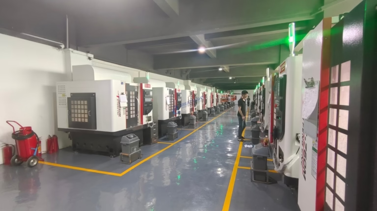
At GreatLight we run 127 high-precision CNC machines across three wholly-owned plants, including 16 simultaneous 5-axis machining centers. Tool setting is the step that keeps that capacity repeatable to ±0.005 mm.
Presetting: measure length and runout before the tool touches the spindle
A tool presetter measures the assembled tool outside the machine. It records gauge length (from the holder's gauge line to the tip) and runout at the cutting edge. Offline measurement keeps the spindle productive and removes operator-to-operator variation.
For a Ø12 mm carbide end mill in a shrink-fit holder, expect runout under 0.005 mm at 3× diameter from the holder face. A collet chuck in good condition usually lands between 0.005 mm and 0.010 mm. If a fresh assembly reads 0.03 mm, stop and find out why before you load it.
Write the measured length onto the tool's setup sheet or let the presetter send it to the controller. Manual transcription is where most length errors start. One digit in the wrong place and the tool plunges into the vise.
Check taper contact with blueing if a holder has been in service for a long time. Contact below roughly 80 percent of the taper length means the holder should be replaced, not shimmed.
- 1Record runout, not just lengthRunout drives chatter and surface finish on long-reach tools.
- 2Re-measure after any crashA pulled tool keeps its length number but loses its geometry.
Holder assembly: the joint that either transmits torque or vibrates
Clean the taper, the holder bore, and the collet with lint-free cloth and a light oil film. A chip the size of a grain of salt under the flange tilts the tool and shows up as a taper or a step on the part.
Match the holder to the operation. Hydraulic and shrink-fit holders give low runout for finishing. Side-lock holders are fine for roughing with flat shank tools but push the tool off center. ER collets are the general-purpose choice and hold well within their torque range.
Torque matters as much as cleanliness. A collet nut under-tightened at 40 N·m instead of 80 N·m lets the tool creep during heavy cuts. Over-tightening distorts the collet and ruins runout. Follow the holder maker's value.
Balance the assembly for high-speed work. Above 12,000 rpm, an unbalanced holder will show vibration marks on the wall of the part even when offsets are perfect.
Offsets and verification: entering the numbers and proving them
Length offset tells the controller where the tip is relative to the gauge line. Radius offset tells it the cutting diameter, plus a wear value you adjust as the tool dulls. Both must match the tool actually loaded in that pocket number.
Verify length with a simple air move. Command the tool to a known Z height above the stock and watch the readout. A 0.1 mm discrepancy is easy to see and cheap to fix. A 0.1 mm error discovered in the part is not.
For radius, cut a test feature and measure it. A Ø10 mm slot that measures 10.03 mm means the radius wear value is off by 0.015 mm. Correct it in the offset table, not by editing the program.
Keep a setup sheet per job. Tool number, holder type, measured length, radius, and wear value. When the job repeats next quarter, the sheet gets you to a good first part in one attempt.
GreatLight inspects 100 percent of parts before shipment, with raw material checks, in-process monitoring, and final inspection. Reports are available on request.
Common set up tools cnc machine mistakes and how to catch them early
The most frequent failure is a tool that was measured but loaded into the wrong pocket. The program calls T07 and gets the T06 length. The first hole is 30 mm too deep or stops in the air. Pocket-to-tool verification takes ten seconds.
Second is thermal drift. A spindle that has been idle for two hours is shorter than one that has been running. On tight-tolerance work, warm up the spindle with a 15-20 minute run-in cycle before touching off, or use a spindle-mounted probe that re-measures on the machine.
Third is worn tool radius left uncorrected. The operator sees a good finish and assumes the size is good. It usually is not. Check a critical dimension every 20-30 parts and update the wear offset.
Fourth is a dirty taper after a tool change. The machine's air blast does not always clear coolant mist from the taper face. Wipe it by hand on high-value jobs.
- 1Wrong pocketVerify tool number against the setup sheet before cycle start.
- 2Cold spindleWarm up or probe on-machine before tight-tolerance cuts.
- 3Stale wear offsetUpdate every 20-30 parts on critical dimensions.
Set up tools cnc machine: step-by-step procedure
- 1Read the setup sheet and pull toolsMatch tool number, geometry, and coating to the program. Confirm the material grade suits the workpiece.
- 2Assemble holders cleanWipe taper and collet with lint-free cloth. Torque the collet nut to the maker's value, typically 80 N·m for an ER32.
- 3Preset length and runoutMeasure gauge length to ±0.001 mm and runout at 3× diameter. Reject assemblies above 0.02 mm runout.
- 4Load and verify pocketsInsert each tool into its assigned pocket. Confirm the number on screen matches the physical pocket.
- 5Enter length and radius offsetsTransfer numbers directly from the presetter or setup sheet. Add a zero wear value as the starting point.
- 6Air-verify lengthMove to a known Z height above stock and compare the readout. Investigate any gap above 0.05 mm.
- 7Cut a first articleMachine one part, measure critical dimensions, and adjust radius wear before releasing the run.
- 8Record and releaseLog the offsets actually used and the first-article results. Start the production run.
Tool setting method: when each one fits
| Method | Accuracy | Best for | Watch out for |
|---|---|---|---|
| Offline presetter | ±0.001 mm length | Repeat jobs, multi-tool programs | Transcription errors into the controller |
| On-machine probe | ±0.002 mm after warmup | Tight tolerances, long cycles | Spindle thermal drift between probes |
| Manual touch-off | ±0.02 mm typical | One-off parts, roughing | Operator variation and paper shims |
| Test cut and measure | ±0.005 mm with care | Verifying radius and wear | Consumes stock and spindle time |
Good tool setting is cheaper than inspection
Preset offline, clean every taper, verify every offset, and cut a first article. That routine holds ±0.005 mm far more reliably than sorting bad parts after the run.
Frequently asked questions
How often should tool offsets be re-checked?
Re-verify length after any tool change, crash, or holder swap. For wear, check a critical dimension every 20-30 parts on production runs.
On long unattended cycles, on-machine probing between parts catches drift before it becomes scrap.
What runout is acceptable for a finishing end mill?
Aim for under 0.005 mm at 3× diameter for finishing. Above 0.02 mm, chatter and finish problems appear quickly, especially on long-reach tools.
Measure with a dial indicator on the flutes, not the shank.
Does tool setting change for 5-axis work?
The principles are the same, but tool length accuracy matters more because the tip position rotates in space. A 0.01 mm length error becomes a 0.01 mm surface error regardless of the axis angle.
Use a presetter and verify with an on-machine probe on critical 5-axis jobs.
Can I set tools while the machine is cutting?
Yes, that is the main reason to use an offline presetter. The spindle keeps running while the next tool is measured and staged.
Keep the staged tools in a numbered rack so pocket loading stays error-free.
What causes a tool to pull out during a cut?
Usually under-torqued collet nuts, oil on the shank, or a worn collet. Clean the shank and collet, then torque to the holder maker's value.
Side-lock holders also let flat-shank tools creep if the set screw is loose.
How do I document tool setup for repeat orders?
Keep a setup sheet with tool number, holder type, measured length, radius, and final wear values. Include the first-article measurement results.
That sheet, plus the same presetter, gets you to a good part in one attempt next time.
Send us your drawing and get a tooling plan back
We review your part, choose the tooling, and quote within 12 hours. Uploads stay confidential, and an NDA is available on request.
12-hour quote100% inspectionNo MOQ
More machining notes from the shop floor
We publish setup notes, tooling trials and inspection data from the factory floor.











