
Metal 3D Printing Design: A 316L Stainless Steel Guide
This guide is for engineers who have a 316L part that is hard to cut, or a design that only works as one printed piece. It covers the design rules that decide whether laser powder bed fusion produces a sound part, and the cases where CNC machining is the cheaper and faster route. Read it before you freeze the model.
In this article
- 1
- 2
- 3
- 4
- 5
- 6
- 7
What matters most in 316L part design
Metal 3D printing design rules that decide success in 316L
Laser powder bed fusion builds a 316L part by melting 10 to 20 μm powder in 20 to 60 μm layers. Each layer is a thin weld bead. That is the whole story behind most design rules. A wall that is too thin cannot absorb the heat of the next pass. An overhang that is too steep has nothing under it to conduct heat away, so the melt pool stays hot and sags. A trapped volume holds powder you cannot remove. Every rule below comes back to heat flow, support, or powder removal.
Start with the material choice. 316L is a low-carbon austenitic stainless with molybdenum for chloride resistance. Printed and stress-relieved, it typically lands near 550 to 620 MPa tensile strength with 35 to 50% elongation, so it bends before it cracks. That ductility is why it is used for manifolds, impellers, and surgical instruments rather than for high-wear tooling. If you need hardness past 40 HRC, 316L is the wrong call.
The table further down compares printed 316L against machined 316L on the points that actually change a sourcing decision. Read that before you commit to an additive process, because a part that looks organic on screen can be a 3-hour job on a 5-axis mill.
One more thing before the rules. Send the model for review while it is still a rough shape. A DFM check on an unfinished model costs nothing and often finds one feature that would have scrapped the build. We return that review within 12 hours with the quoted price.
- 1Powder layer20 to 60 μm typical; finer layers give better surface, slower builds.
- 2Inert atmosphereArgon keeps oxygen low so the melt pool does not oxidize.
- 3Stress reliefRequired before the part is cut from the plate, or it warps.
Wall thickness, holes, and clearances in printed 316L
Minimum wall thickness sits around 0.4 mm for a vertical wall, and 0.6 mm is a safer target for anything load-bearing. The reason is not the laser spot size. It is heat. A 0.2 mm wall has almost no cross-section to pull heat into the substrate, so the melt pool overheats, the wall bows, and porosity climbs. If your design needs a thin membrane, thicken it locally with a rib and machine the rib away later if the function allows.
Small holes are the second common trap. A 1 mm vertical hole will print, but expect the diameter to come out undersized by 0.1 to 0.2 mm because of unmelted powder sticking to the wall. Design the hole at 1.1 to 1.2 mm and ream it after. Horizontal holes above roughly 6 mm need a teardrop or diamond profile, since the top of a round hole is an unsupported overhang. Below 6 mm, a round hole usually bridges without trouble.
Clearances matter on any assembly that prints as one piece. Leave 0.2 to 0.3 mm between surfaces that must move or separate. Anything tighter fuses once the powder sinters around it. Anything looser leaks powder into the gap and it will not come out.
Threads are usually a poor fit for as-printed 316L. A printed M6 thread will hold, but the flanks are rough and the pitch diameter drifts. Print a plain hole at the tap drill size and cut the thread after, or use a heat-set insert.
- 1Minimum wall0.4 mm vertical, 0.6 mm preferred for loaded parts.
- 2Hole compensationAdd 0.1 to 0.2 mm to small round holes, then ream.
- 3Running clearance0.2 to 0.3 mm between surfaces that must not fuse.
Build orientation and self-supporting angles
Orientation is the single biggest lever you have. It sets surface finish on the critical faces, the amount of support, the build height, and the residual stress pattern. A face that points down toward the plate will be rough and may need grinding. A face that points up is smooth. If one face of the part is a sealing surface, orient it up.
The usual guidance is that overhangs below 45 degrees from vertical are self-supporting in 316L. Treat that as a starting point, not a law. Thick sections hold heat and sag earlier, so a 40-degree overhang on a 20 mm wall may still need support. Sharp internal corners concentrate stress, so radius them at 0.5 mm minimum and the crack risk drops.
Round parts are often best built at an angle. Tilting a cylinder 30 to 45 degrees keeps the downskin small and lets you break supports off with a hand tool. Building it flat on the plate puts a large rough surface on the bottom and a heavy support grid you have to cut away.
Long thin parts are the exception. A shaft built vertically is stable but the layers stack in the weak direction, and it can snap at the build plate. Build it horizontally with supports, or accept the anisotropy and design a larger section.
- 1Self-support limit45 degrees from vertical is a guide. Thick sections need less.
- 2Critical facesPoint sealing and sliding surfaces upward.
- 3Internal cornersRadius 0.5 mm or more to avoid stress risers.
Support removal, heat treat, and finishing after the build
A printed 316L part is not finished when the build stops. It stays bolted to the plate through a stress-relief cycle, usually 2 hours at 600 to 650 °C in vacuum or argon, so the residual stress from rapid cooling does not warp it when it is cut free. Skip that step and a thin part will bow the moment the wire cut releases it.
Support removal comes next. Hand tools take the bulk off, then a cut-off wheel or wire EDM handles the root. The witness marks left behind are the real cost driver, so the fewer attachment points you design in, the cheaper the part. Where a support touches a cosmetic face, plan a machining allowance of 0.3 to 0.5 mm and face it afterward.
As-built surface is around Ra 8 to 12 μm on upskin, worse on downskin, and rough on any supported face. Bead blasting brings it to a uniform matte. If the part needs a seal or a bearing fit, machine that face. Our finishing shop can take printed 316L to Ra 0.8 to 1.6 μm on specified faces, and to Ra 0.2 to 0.8 μm where a lapped or polished surface is required.
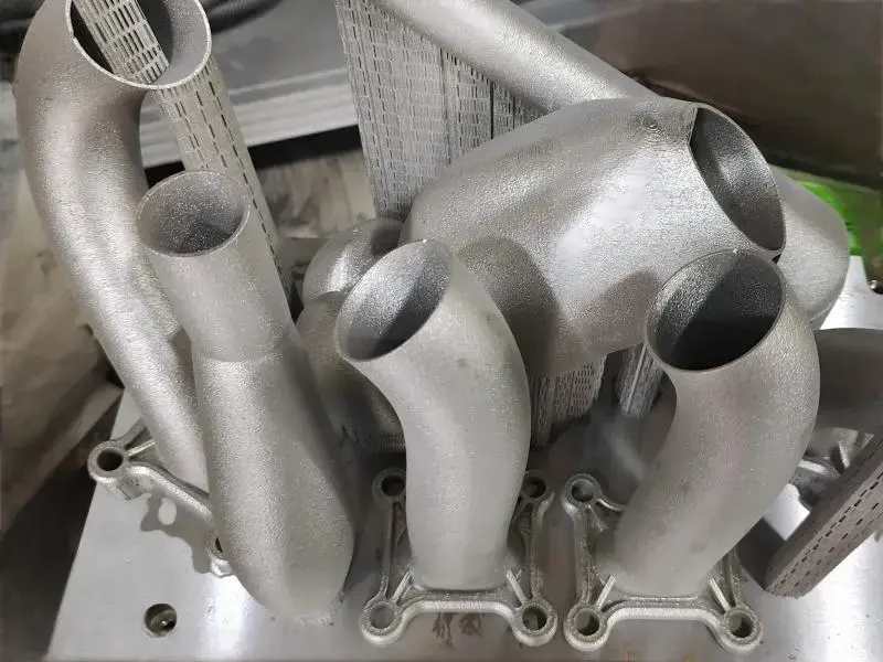
Internal channels are the reason many parts get printed at all. They come out rough and they trap powder. Design a 4 to 6 mm channel with no blind ends, give it two open ports, and plan a flow-through rinse plus ultrasonic clean. A channel you cannot inspect is a channel you cannot trust.
- 1Stress relief2 h at 600 to 650 °C before cutting from the plate.
- 2Machining allowance0.3 to 0.5 mm on faces where supports attach.
- 3Channel cleaningTwo open ports, 4 to 6 mm bore, ultrasonic rinse.
When printed 316L is the wrong answer
Additive is not automatically better because it is newer. Printed 316L costs more per part than machined 316L for simple geometry, and the surface is worse. If a part can be reached by a cutter from a few directions, CNC is faster and cheaper. That covers most brackets, housings, flanges, and shafts.
Printing wins when the geometry has internal channels that cannot be drilled, when the part is a single piece replacing an assembly of five, or when the quantity is low and the tooling cost of another process is hard to justify. It also wins when the part is topologically optimized and the weight saving is the point.
There is a middle path that engineers often miss. Print the blank, then machine the critical features. A printed 316L body with machined bores, faces, and threads gets the internal geometry of additive and the tolerance of CNC. At GreatLight we run that route on mill-turn and 5-axis centers with an accuracy of ±0.005 mm on the machined features, so the printed and cut portions can be held to different standards on purpose.
Decide with the print orientation and the tolerance callout in front of you. If more than a third of the surfaces need machining anyway, the print is probably not paying for itself. If the printed geometry is what creates the function, it is.
- 1Choose printingInternal channels, consolidated assemblies, low volume, weight-driven designs.
- 2Choose CNCSimple geometry, tight tolerances on most faces, higher quantities.
- 3HybridPrint the body, machine bores and sealing faces to ±0.005 mm.
Printed 316L against machined 316L
Use this to pick a route before the model is frozen.
| Factor | Printed 316L (LPBF) | Machined 316L |
|---|---|---|
| Best geometry | Internal channels, organic shapes, one-piece assemblies | Prismatic parts reachable by a cutter |
| As-built surface | Ra 8 to 12 μm upskin, rougher on downskin | Ra 1.6 to 3.2 μm as machined |
| Achievable tolerance | ±0.1 mm typical, ±0.05 mm on selected faces | ±0.005 mm on machined features |
| Wall or feature floor | 0.4 mm wall, 1 mm hole with reaming | Limited by tool reach, not wall |
| Lead time | Build plus heat treat plus support removal | Parts ship in 3 to 5 days |
| Cost driver | Build height, support volume, post-processing | Machine time and setup count |
| Quantity fit | One prototype to low hundreds | One prototype to 10,000+ parts |
| Heat treatment | Stress relief required before cut-off | Not usually needed for 316L |
Which route should you pick
If the function comes from internal channels or a consolidated one-piece shape, print in 316L and machine only the critical faces. If the geometry is reachable by a cutter and most surfaces carry a tolerance, machine it from 316L bar and skip additive entirely. When the part is split between the two, print the body and let us hold ±0.005 mm on the machined features.
Questions engineers ask before a 316L build
What is the minimum wall thickness for printed 316L?
0.4 mm is the practical floor for a vertical wall, and 0.6 mm is a safer target for anything that carries load. The limit comes from heat, not from laser spot size. A very thin wall cannot conduct heat into the substrate, so the melt pool overheats and the wall bows.
If the design needs a thin membrane for function, thicken it with a local rib and machine the rib away later where the geometry allows.
Can I print threads directly in 316L?
You can, but the flanks come out rough and the pitch diameter drifts, so the fit is inconsistent. For anything that has to torque down or seal, print a plain hole at the tap drill size and cut the thread after, or use a heat-set insert.
Laser marking and engraving on printed 316L needs a minimum character height of 1.5 mm to stay legible after bead blasting.
How do I get powder out of internal channels?
Give the channel two open ports so a rinse can flow through, and keep the bore at 4 to 6 mm. Blind ends trap powder that no rinse will reach.
Plan an ultrasonic clean after support removal. A channel you cannot inspect is a channel you cannot trust.
Does printed 316L need heat treatment?
Yes. The part stays on the build plate through a stress-relief cycle, usually 2 hours at 600 to 650 °C in vacuum or argon, before it is cut free. Without it, residual stress from rapid cooling warps thin sections the moment the wire cut releases them.
That cycle is not a solution treatment. It relieves stress, it does not change the as-built grain structure.
How close can printed 316L hold a tolerance?
Expect around ±0.1 mm on as-built features, and ±0.05 mm on a face that is machined after printing.
If a feature needs better than that, it should be cut. Our 5-axis and mill-turn centers hold ±0.005 mm, so a hybrid print-and-machine part can carry two different tolerance classes on purpose.
Can you handle both the printing and the machining?
Yes. We run 316L among other stainless grades and finish printed parts on 127 high-precision CNC machines, including 16 simultaneous 5-axis centers and a Ø400 mm rotary table.
Quotation and a free DFM analysis come back within 12 hours, and production can start within 24 hours of approval. Parts ship in 3 to 5 days, with 100% inspection before shipment and reports on request.
Send the model before you freeze it
Upload a STEP file and we will return a DFM review, a process recommendation, and a price within 12 hours. No minimum order quantity, from one prototype to a 10,000+ part run. Uploads stay confidential and an NDA is available on request.
12-hour quote100% inspectionISO 9001:2015NDA on request
More from GreatLight
We publish setup notes, tooling trials and inspection data from the factory floor.











