
Night Vision Goggle Housing CNC
A housing holds the optics, the intensifier tube and the battery in one rigid, sealed body. This page explains what actually decides whether it works: wall thickness, bore alignment, sealing surfaces, material and coating. Written for design engineers and buyers who need to judge a quote or a first article.
In this article
- 1
- 2
- 3
- 4
- 5
- 6
- 7
What the housing geometry actually has to do
A night vision goggle housing is not a box with holes. It carries three optical axes, keeps them parallel to each other, holds an image intensifier tube in a fixed seat, and seals against rain, dust and sweat. Every one of those jobs is a dimensional problem before it is a styling problem.
The two tube bores are the tightest feature on most parts. They set interpupillary distance, so a shift of 0.05 mm in one bore moves the exit pupil. On collimated binoculars this shows up as a merge error the user cannot correct by adjusting the diopter.
Mounting bosses for the lens retainers and the tube seat usually land in the same setup as the bores. If they are machined in a second operation, the stack-up between setups eats the tolerance budget before the part is even measured.
The battery compartment and the helmet interface are the other load paths. They do not need optical accuracy, but they do need flatness, or the housing rocks on the mount and the user loses the eyeline.
- 1Optical boresParallelism and position drive the image, not the finish
- 2Tube seatDepth control sets focus travel, usually a shoulder face
- 3Helmet interfaceFlatness matters more than tolerance grade
- 4Battery baySealing land, thread and contact position in one setup
Wall thickness, ribs and the weight problem
Users wear night vision goggles for hours, so mass at the front of the helmet is the design driver behind almost every housing. Engineers thin the walls, then add ribs to get stiffness back. That is the right instinct, but it moves the risk into machining.
A 1.2 mm wall on 7075-T6 aluminium looks fine on screen. On the machine it deflects under cutting force, and the floor of a deep pocket can go 0.1 mm thin in the middle without any alarm. Once the wall is thin, the part also moves after clamping release.
Ribbing helps if the ribs are tall enough to reach the neutral axis of the section. Short, wide ribs add mass and almost no stiffness. Thin, deep ribs work, but the cutter has to reach the floor without chattering, which usually means a smaller tool and more passes.
Magnesium alloys such as AZ31B and AZ91D cut this problem in half by weight, and GreatLight machines them. They also bring chip handling and fire risk, so the shop needs the right suppression setup before the first cut.
- 1Keep floors uniformVarying floor thickness is where vibration starts
- 2Ribs, not wallsStiffness per gram is better in tall thin ribs
- 3Expect spring passesThin walls need a light final cut after stress relief
Sealing faces and surface integrity
An NVG housing is expected to survive rain, dust and salt spray, and many builds are purged with dry nitrogen. That means the seal is a machined surface, not a rubber part alone. A gasket can only compensate for a groove that is already flat and continuous.
Groove depth and width set the squeeze on the O-ring or molded seal. A groove that is 0.05 mm shallow still seals. A groove with a burr at the corner does not, because the burr lifts the seal off the land on one side.
Micro-porosity is the slow failure. Cast or additively made blanks can hide pores that open up during anodizing or after a few thermal cycles. Machined pockets that break into a pore create a leak path that no gasket fixes.
Surface finish on the land should sit around Ra 0.8–1.6 μm for a molded seal and can go finer, down to Ra 0.2–0.8 μm, where a metal-to-metal or face seal is used. Rougher than Ra 3.2 μm and the seal starts to weep at low temperature.
- 1Groove depthControls squeeze; measure after coating, not before
- 2Edge breakA 0.2–0.3 mm chamfer protects the seal
- 3Coating buildHard anodize adds thickness and can close a groove
Material choice and what it costs you on the machine
Aluminium 7075-T6 is the default for structural housings. It gives the best strength-to-weight ratio among the common alloys and machines cleanly at high spindle speed. It is also less corrosion resistant than 6061, so it normally goes to hard anodize or chem film.
6061-T6 is the cheaper, more forgiving option. If the housing is not weight critical and the wall stays above 2 mm, 6061 does the job and takes anodize evenly. For a first article or a small batch, that difference matters more than the last gram.
Titanium Ti-6Al-4V and 17-4PH stainless appear when the housing has to survive impact or a corrosive environment. Both cut slowly. Titanium needs low cutting speed and plenty of coolant, and any thin floor becomes a chatter problem.
Carbon fibre and hybrid composites are used where weight dominates, but they change the design rules. Threaded inserts, galvanic isolation and edge sealing all become separate features, and they rarely come from the same shop as the metal version.
- 17075-T6Best stiffness per gram, needs corrosion protection
- 26061-T6Easier to machine and anodize, heavier section
- 3Magnesium AZ31B/AZ91DLightest metal option, strict chip control
- 4Ti-6Al-4VImpact and corrosion resistance, slow cutting
Five-axis machining, deep pockets and setup count
Most housings have features on five or six faces. Every extra setup adds a datum shift. A part machined in five setups has five chances to lose 0.02 mm before anyone measures the optical bores.
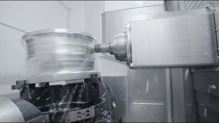
Simultaneous five-axis machining lets the shop reach angled lens seats, undercut ribs and blend radii in one clamping. It also keeps the bores and the mounting bosses in the same coordinate system, which is the main reason the alignment holds across a batch.
Deep pockets are the counterexample. A pocket 60 mm deep and 25 mm wide needs a long tool, and a long tool deflects. The practical fix is a roughing pass with a larger radius cutter, then a semi-finish at reduced stepover, then a light finish pass.
For prototypes, printed or cast blanks can be finished on the critical faces only. The printed body carries the shape and the machined faces carry the tolerance. That splits the cost in a useful way, as long as the print is stress-relieved before the finish cut.
- 1One setup, many facesFewer datums, tighter bore-to-boss alignment
- 2Rough, semi-finish, finishThree passes beat one heavy pass in deep pockets
- 3Hybrid blanksPrint or cast the body, machine the optical faces
How to verify a housing before it ships
Inspection should follow function. The first check is not the outside profile; it is the relationship between the two tube bores and the lens seat faces. Those are the dimensions that decide whether the goggle merges images.
Coordinate measuring machines handle the bores and the seat faces. For the sealing groove, a profile scan or a dedicated gauge is faster and closer to how the seal actually sits. Depth measurement has to happen after coating, because hard anodize can add several micrometres per surface.
Leak testing is a separate gate. A pressure decay test on the assembled or partially assembled housing catches a pore or a groove defect that dimensional inspection will pass. It should be done before final cosmetics, not after.
GreatLight inspects 100% of parts before shipment and can supply raw material, in-process and final reports on request. For a defense-adjacent program, the inspection plan is worth agreeing on before the first chip is cut.
- 1Bore relationship firstPosition and parallelism before cosmetics
- 2Groove after coatingMeasure the seal land in its final state
- 3Leak test as a gatePressure decay catches what CMM cannot
Which route fits which housing
Pick the row that matches your part, not the row with the best numbers.
| Housing type | Best route | Watch for |
|---|---|---|
| Monocular, 6061-T6, wall above 2 mm | 3-axis plus 4-axis indexing | Setup count raises bore-to-boss error |
| Binocular, 7075-T6, thin ribbed walls | Simultaneous 5-axis | Floor deflection; spring pass needed |
| Magnesium AZ91D, weight critical | 5-axis with chip management | Fire risk and chip evacuation |
| Titanium or 17-4PH impact body | 5-axis, low cutting speed | Tool wear and long cycle time |
| Prototype, geometry not frozen | Printed blank, machined faces | Stress relief before final cut |
| Production run, 500+ parts | 5-axis with dedicated fixture | Fixture wear drifts over a batch |
The short version
If the housing is weight critical and the walls are thin, go to 7075-T6 or magnesium on simultaneous 5-axis and accept the higher piece cost. If the walls stay above 2 mm and the budget is tight, 6061-T6 on indexed 4-axis will meet the same optical tolerances for less money.
Questions engineers ask next
What tolerance can a night vision goggle housing actually hold?
On the optical bores and mating faces, ±0.005 mm is achievable on a stable setup with temperature control.
On non-critical features such as the battery bay or the outer profile, ±0.05 mm is usually enough and costs much less.
Can a 3D printed housing be good enough for field use?
For a fit check or a prototype build, yes. Printed bodies let you test ergonomics and helmet balance before tooling.
For a sealed, drop-tested unit, the printed body usually becomes a blank that is machined on the optical and sealing faces, not a finished part.
How do you stop thin walls from moving after machining?
Rough the part, let it rest, then finish. Removing 70–80% of the material in the first pass releases most of the internal stress.
The finish pass takes a light cut, often 0.1–0.2 mm, on a part that has already stopped moving.
Does hard anodizing change the sealing groove?
Yes. A hardcoat layer grows into and out of the surface, so a groove measured before coating will be tighter after.
Machine the groove to allow for the coating, or mask it and cut it after coating if the seal is sensitive.
What surface finish do the lens seats need?
A seat that locates a lens or a retainer usually sits at Ra 0.8–1.6 μm. That is smooth enough to seat repeatably without polishing.
Mirror finishes below Ra 0.2 μm are rarely needed on a housing and add cost without improving alignment.
What information do you need to quote a housing?
Send the 3D model, the 2D drawing with the tolerance callouts on the optical features, the material, the finish and the quantity.
We return a quotation and a free DFM analysis within 12 hours. Production can start within 24 hours of approval, and uploads stay confidential under NDA on request.
Send the model, get a DFM read in 12 hours
We machine aluminium, magnesium, titanium and stainless housings on 127 CNC machines, from one prototype to a 10,000-part run. Upload the files and an engineer will flag the thin walls and tight bores before quoting.
12-hour quote100% inspectionNDA on requestNo minimum order quantity
More from the shop floor
We publish setup notes, tooling trials and inspection data from the factory floor.











