
CNC Finishing Machine: Where Final Dimensions Get Locked In
Roughing moves metal fast. Finishing is what decides whether a part assembles, seals and lasts. This page explains how a CNC finishing machine works, what it can and cannot hold, and how to tell when a part belongs on a finishing pass and when it does not.
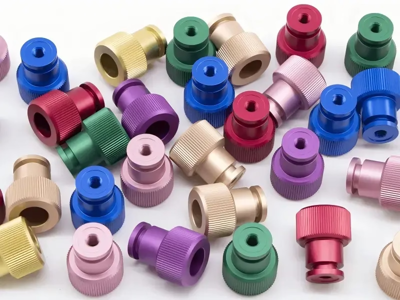
What a CNC Finishing Machine Actually Changes
Roughing removes most of the stock. It leaves a part that is close to size but still carries chatter marks, tool wear footprints and a few hundredths of deflection. A CNC finishing machine takes that near-net shape and cuts the last 0.2–0.8 mm. The target is not speed. It is the final dimension, the geometric tolerance and the surface texture the drawing calls out.
The distinction matters commercially. A part can pass a first-article check and still leak, seize or vibrate out of tolerance after a few hundred cycles because the finishing pass was too aggressive. Finishing controls three things at once: form (straightness, roundness, flatness), size (±0.005 mm on our 5-axis centers) and finish (down to Ra 0.2–0.8 μm when the geometry allows).
Think of it as the last 5 percent of the cut that decides 90 percent of the field behavior. That is why finishing is planned before the first tool touches the stock, not added at the end when the part is already at nominal size.
A finishing pass is also the most sensitive cut in the whole cycle. Low radial engagement means the tool can deflect just as easily on a light pass as on a heavy one, and small chips mean heat leaves with the tool instead of the chip. Both effects show up directly in the measured profile.
- 1FormStraightness, roundness, flatness, perpendicularity
- 2SizeHeld to ±0.005 mm on qualified setups
- 3FinishRa 0.2–0.8 μm on stable geometries
- 4FunctionSealing, bearing fit, fatigue life, appearance
CNC Finishing Machine Setup: The Variables That Move the Result
On a finishing pass the cut is shallow but the process is not forgiving. Chip load drops, so the tool edge rubs rather than shears if the feed is set too low. Ra rises, and the surface work-hardens. In aluminium 6061 and 7075 we keep the finishing chip load in a range that cuts cleanly rather than polishing the surface with a dull edge. In 316L and 17-4PH the same logic holds but the window is narrower and heat matters more.
Spindle speed and feed have to move together. Raising rpm without raising feed per tooth thins the chip and burns the edge. The practical signal is chip color and sound, plus the surface after the pass. If the finish looks smeared rather than cut, the feed is too low or the tool has lost its edge.
Runout is the quiet killer. A tool holder with 0.01 mm runout will cut one flute deeper than the others and leave a visible pattern in the finish. On finishing work we check holder runout at the spindle before the pass, not on the bench. Thermal growth during a long cycle also shifts Z, so we plan a warm-up cycle and keep the coolant steady.
Fixturing decides whether the finish survives the cut. A part held on three points with light clamping will move as the material is released. For thin walls and long parts, we use supports that match the final geometry and, where the drawing allows, leave tabs that are cut last. Clamping pressure is set to hold the part, not to bend it.
Tool path style feeds directly into the finish. A constant-engagement path keeps the load stable through corners, which keeps Ra consistent. Where a surface must be smooth across a blend, we use a continuous 5-axis path rather than a series of 3-axis passes, so the tool stays tangent to the surface and no step marks appear at the seams. The trade-off is programming time, and it is almost always worth it on sealing faces and bearing bores.
Material Behavior on the Finishing Pass
Aluminium finishes fast. 6061 and 6082 cut cleanly, hold a fine Ra and are stable enough that a light pass does not distort the part. 7075 is stronger but more prone to burrs on edges, so we plan a deburring pass into the path. Thin aluminium walls still move after the cut, so we check them after a settling period rather than at the machine.
Stainless is where finishing strategy changes most. 304 and 316 work-harden if the tool rubs, so the pass must cut, not scrape. 17-4PH in the H900 condition gives a hard, stable surface, but tool wear over a long run will drift the size, so we track wear offsets between parts rather than trusting a single setup. 440C approaches the range where a carbide edge struggles to keep Ra low and a grinding or lapping step becomes the honest answer.
Titanium TC4 (Ti-6Al-4V) reacts to heat. The finishing pass runs slower with more coolant, and the surface can still show a light smear if the edge is dull. We change tools on a count, not on a feeling. Magnesium AZ31B and AZ91D cut beautifully but chip control and fire safety dominate the setup, so finishing passes are short and the chip is cleared continuously.
Plastics and composites behave differently again. POM and PEEK cut cleanly but hold internal stress that releases after machining, so a finished dimension measured hot is not the finished dimension. Carbon fibre needs diamond or coated tooling and dust extraction, and the surface quality depends more on tool sharpness than on speed. Copper and brass finish easily but are soft enough that a chip can drag across the surface and mark it, so chip evacuation is part of the finish plan.
When a CNC Finishing Machine Is Not the Right Answer
Finishing is not a universal fix. If the drawing asks for Ra 0.05 μm on a hardened steel bore, a milling pass will not get there. Grinding, honing or lapping is the correct process. If the part is a thin, large plate that springs after every cut, no amount of finishing skill will hold flatness without a stress-relief step first. In those cases the honest answer is a process change, not a slower pass.
Deep pockets and long reach tools are another boundary. A tool that is 10 times its diameter long will deflect, and the finish will show it. We can reduce the deflection with a smaller stepover, a lighter pass and a shorter tool, but the geometry may simply not allow a mirror finish. The right move is to tell the customer early and agree on a realistic Ra.
Very hard materials above roughly 45 HRC are also a boundary for milling. Carbide can cut them, but the tool life cost per part climbs quickly. For a one-off, milling is still practical. For a run of thousands, the cost comparison starts to favor a ground or EDM process for the final surface.
There is also a time boundary. A finishing pass on a complex 5-axis surface can take longer than the roughing that removed 20 times the material. If the schedule is tight, we look at whether the finish requirement can be split, with a machined finish on functional faces and a coarser finish on non-critical surfaces.
The final boundary is inspection. If a finish cannot be measured in a repeatable way, it cannot be controlled. For fine finishes we use surface roughness comparison and, where the customer requires it, a roughness tester with a documented cut-off length. Reports are available on request.
- 1Below Ra 0.2 μmGrinding or lapping is the realistic route
- 2Hardened steel above 45 HRCMilling is possible but tool cost rises fast
- 3Thin, large platesStress relief before finishing, not after
- 4Long reach toolsDeflection limits the achievable Ra
Finishing Route by Surface Requirement
Use this table to pick the process before quoting, not after the first part fails.
| Target surface | Usual process | Typical Ra | When it fits |
|---|---|---|---|
| As-machined face | 3-axis finish pass | Ra 1.6–3.2 μm | Brackets, covers, non-sealing faces |
| General functional face | 3-axis or 4-axis finish pass | Ra 0.8–1.6 μm | Bearing seats, locating faces |
| Fine functional face | 5-axis finish pass | Ra 0.2–0.8 μm | Sealing faces, sliding surfaces |
| Fine finish on hardened bore | Grinding or honing | Below what milling holds | Hardened steel above 45 HRC |
| Cosmetic aluminium panel | Finish pass plus bead blast | Uniform matte look | Enclosures, visible covers |
| Sealing face on stainless | Light finish pass, sharp tool | Ra 0.8–1.6 μm | 316L and 17-4PH fluid parts |
The Rule We Use
If the surface is functional, specify the finish and let us choose the process. If the surface is cosmetic, specify the look and we will match it with a finish pass plus a surface treatment. Do not put a grinding-level Ra on a milling drawing and expect a milled part to pass.
CNC Finishing Machine Questions Engineers Ask
How tight a tolerance can a CNC finishing machine hold?
On qualified setups with stable geometry and controlled temperature, our 5-axis centers hold ±0.005 mm (±0.0002 in). That is a process capability, not a default on every feature. Very thin walls, long unsupported sections and deep pockets will open that up.
If a feature needs tighter than ±0.005 mm, we will say so during DFM and propose a different route rather than quote a number the process cannot repeat.
What surface finish can you achieve without grinding?
On stable geometries with the right material and tool, milling reaches Ra 0.2–0.8 μm. General functional faces usually land at Ra 0.8–1.6 μm, and as-machined cosmetic faces at Ra 1.6–3.2 μm.
Below Ra 0.2 μm is a grinding or lapping job. We would rather tell you that up front than run a slow pass that cannot get there.
Does a slower finishing pass always give a better finish?
No. Too low a feed per tooth makes the edge rub instead of cut. The surface smears, work-hardens and can end up rougher than a faster pass would have produced.
The finish comes from a sharp edge, stable chip load and low runout. Speed is only one of the four variables.
How do you control finish across a batch, not just on one part?
Tool wear is tracked by count, not by ear. When a finishing tool reaches its limit we change it before the size drifts, and we verify with in-process checks. Raw material is checked on receipt, and every part gets a final inspection before shipment.
Reports are available on request, including dimensional results and surface roughness where the drawing calls for it.
Can you finish a part made from a material you have not run before?
Usually yes, but we treat it as a new process. We run a test cut, measure the result, and adjust the pass before committing to the batch. Magnesium and some composites need specific chip and dust handling, so those start with a process review.
For a single prototype this adds a short setup step. For a production run it is what keeps the finish repeatable.
What do you need from us to quote a finishing job?
A 3D model plus a 2D drawing with the tolerances, surface finish callouts and any datum scheme. Material and heat treatment condition matter, because 17-4PH in H900 finishes differently from the annealed condition.
We return a quotation and a free DFM analysis within 12 hours. Uploads are secure and confidential, and an NDA is available on request.
Send the Drawing, Get a Finishing Plan
Upload your part and we will come back with a quotation, a DFM analysis and a finishing route that matches the drawing.
12-hour quote±0.005 mm100% inspectionNo minimum order
More from the shop floor
We publish setup notes, tooling trials and inspection data from the factory floor.











