
Russian mold CNC processing: how tight-tolerance mold parts get machined
This page covers the mechanics behind Russian mold CNC processing: why mold inserts, cores and slides are cut on 5-axis machines, where 3-axis still wins, and how to judge a quote before you send a drawing. Written for tooling engineers and buyers who need parts that fit the first time.
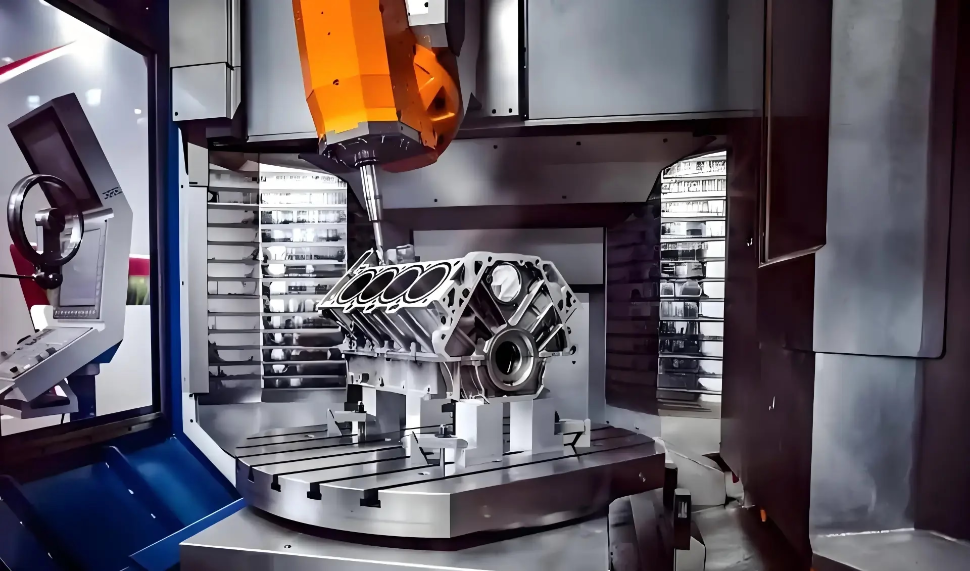
What makes mold work different from general CNC
A mold is not one part. It is a stack of plates, inserts, cores, slides and lifters that must close on each other thousands of times without flashing. Every mating surface is a datum for the next one. That is why Russian mold CNC processing is judged less on a single dimension and more on how the cavity, the parting line and the ejector plate agree with each other after assembly.
The cutting conditions are also unusual. Mold steel arrives pre-hardened at 28–32 HRC or fully hardened at 48–52 HRC, so tool load stays high and heat builds fast in small corners. Deep ribs and thin walls deflect under that load. A 1.5 mm rib that measures correctly on the machine can spring back 0.03 mm once the cutter leaves.
Most failure in mold machining comes from access, not from the control. A tool that can reach a corner still needs a holder that clears the wall behind it. When the holder rubs, the machinist shortens the tool, the tool deflects, and the corner comes out tapered.
- 1Stacked tolerancesCavity, core and plate datums chain together.
- 2Hard material28–52 HRC steel changes feeds and depths of cut.
- 3Thin featuresRibs under 2 mm deflect during and after cutting.
- 4Access limitsHolder clearance often sets the real limit.
Why 5-axis setups hold mold geometry better
On a 3-axis machine, a deep cavity is cut with the tool pointing straight down. The machinist then re-fixtures the block to reach the side walls. Each re-fixture adds a positioning error. On a 4,000 mm mold base, a tenth of a degree in rotation can move a corner by more than 0.05 mm.
A simultaneous 5-axis center tilts the tool instead of the part. The same insert is cut from four or five directions in one setup, so the parting line and the cavity share one coordinate system. GreatLight runs 16 simultaneous 5-axis machining centers, with a Ø400 mm rotary table for smaller inserts and travels up to 4,000 × 400 × 150 mm for long bases.
The gain is not only accuracy. Short, stubby tools cut faster and last longer than long reach tools. Tilting the spindle lets a Ø12 mm tool do work that would need a Ø6 mm tool in a 3-axis setup. Cycle time drops and the surface finishes cleaner.
- 1Fewer setupsOne coordinate system for cavity and parting line.
- 2Stiffer toolsShorter gauge length means less chatter.
- 3Better reachTilted spindle clears undercut walls.
When 3-axis is still the right call
Not every mold plate needs five axes. A flat backing plate with drilled and tapped holes is faster and cheaper on a 3-axis mill. So is a simple open pocket where the tool axis never has to change. Putting that work on a 5-axis center wastes spindle time and adds programming hours for no gain.
The practical split is geometry driven. If the part has undercuts, deep ribs, compound angles or a curved parting line, five axes pay for themselves. If it is prismatic with through-holes, three axes win on cost. GreatLight keeps 27 three-axis machines and 12 four-axis mills alongside the 5-axis cells for exactly this reason.
Hardness matters too. Above 45 HRC, roughing with a large tool then finishing with a small ball nose is standard. Below 35 HRC, a heavier depth of cut removes stock faster and the finishing pass stays light. Choosing the wrong split leaves either a slow cycle or a chipped corner.
- 13-axis fitFlat plates, open pockets, drilled hole patterns.
- 24-axis fitCylindrical cores, helical ribs, index work.
- 35-axis fitUndercuts, compound angles, curved parting lines.
Steel grades and what they do to the cut
P20 and 1.2311 arrive pre-hardened near 30 HRC and machine predictably. They are the default for large plastic injection molds where wear is moderate. H13 and 1.2344 run harder, hold up in die casting and glass-filled resin, and need slower feeds with more attention to heat at the cutting edge.
Stainless grades behave differently again. 420 and 440C are used for wear inserts and slides; both work-harden if the cutter dwells, so the feed per tooth must stay above a floor rather than dropping to a crawl. 17-4PH (SUS630) is common where corrosion resistance and hardness are both needed.
On the aluminum side, 7075 and 6061 cover most prototype mold work and check fixtures. Copper and beryllium copper appear in conformal cooling inserts and welding electrodes, where thermal conductivity does the job. Beryllium copper needs dust control and a clear shop rule; we machine it wet and keep the swarf contained.
For hard milling above 50 HRC, the finish pass usually runs a coated carbide ball nose at 0.05–0.15 mm stepover to reach Ra 0.2–0.8 μm. Below that hardness, Ra 0.8–1.6 μm comes off the machine without extra work.
Inspecting a mold insert before it ships
Mold parts are inspected against the 3D model, not against a 2D print alone. CMM probing covers the cavity surfaces, the parting line and the dowel pin locations. For deep ribs and narrow slots, an optical or laser scan fills in what a touch probe cannot reach.
Fit checks matter as much as dimensions. Slides are assembled against their wear plates, ejector pins are checked for height, and the core is set into the cavity to confirm shutoff. A part that passes inspection on the bench but will not close in the press has not been checked properly.
GreatLight inspects 100% of parts before shipment, with raw material verification, in-process monitoring and a final inspection report on request. Tolerances are held to ±0.005 mm (±0.0002 in) on critical mold features. The historical qualification rate is 99.99%, which is the number that decides whether a tool goes into the press or back onto the machine.
- 1CMMCavity, parting line, dowel and pin locations.
- 2ScanDeep ribs and slots a probe cannot touch.
- 3Assembly checkSlide fit, pin height, core shutoff.
Which machine setup fits which mold feature
Use the feature shape and hardness to pick the setup before quoting.
| Mold feature | Best setup | Typical tolerance | Watch out for |
|---|---|---|---|
| Flat backing plate | 3-axis | ±0.02 mm | Hole position stack-up |
| Open pocket, straight walls | 3-axis | ±0.01 mm | Corner radius vs. tool size |
| Cylindrical core | 4-axis | ±0.01 mm | Runout at the chuck end |
| Helical rib on a core | 4-axis | ±0.01 mm | Chatter on thin ribs |
| Deep cavity, undercut | 5-axis simultaneous | ±0.005 mm | Holder clearance behind wall |
| Compound-angle slide | 5-axis simultaneous | ±0.005 mm | Datum shift between setups |
| Curved parting line | 5-axis simultaneous | ±0.005 mm | Blend marks on the shutoff |
| Hardened insert, 48–52 HRC | 5-axis + hard milling | ±0.005 mm | Tool wear near thin corners |
Pick the setup from the geometry, not the machine list
If the feature has undercuts, deep ribs or a curved shutoff, go 5-axis and accept the programming hours. If it is prismatic and open, go 3-axis and put the savings into the finishing pass. The wrong choice shows up as either a slow cycle or a mold that flashes.
Questions engineers ask before sending a mold drawing
What does Russian mold CNC processing actually cover?
It covers CNC machining of mold components: cavities, cores, inserts, slides, lifters, wear plates and mold bases. The work is defined by the geometry and the steel hardness, not by the origin of the mold design.
In practice that means 3-axis, 4-axis or simultaneous 5-axis milling, plus turning, drilling and finishing on the same part.
What tolerance can you hold on a deep cavity?
±0.005 mm (±0.0002 in) on critical mold features such as the parting line, shutoff and dowel locations, when the geometry allows a rigid setup.
Deep ribs under 2 mm wide are the exception. Tool deflection sets the limit there, and we will tell you the achievable number before quoting rather than after.
Which materials do you machine for mold work?
Aluminum 6061, 7075 and 6082 for prototypes and check fixtures; stainless 420, 440C, 17-4PH for wear parts; P20 and H13-class tool steels for production molds; copper and beryllium copper for conformal cooling and electrodes.
Full grade lists are on the materials page, and any special grade can be quoted from a mill certificate.
Can you start from a mold design we send as STEP?
Yes. A STEP or Parasolid model plus a 2D print for the critical dimensions is enough. We run a free DFM analysis and return a quotation within 12 hours.
If a feature cannot be machined as drawn, we flag it with a suggested change instead of quietly cutting something different.
How do you handle confidentiality on mold drawings?
Uploads stay secure, and an NDA is available on request before any file is transferred. Access is limited to the engineers working on the quote and the job.
If you need the tooling split across two suppliers, we can quote only the inserts and leave the base out of scope.
What is the smallest order you take?
There is no minimum order quantity. A single replacement insert and a 10,000-part run are both quoted the same way.
Production can start within 24 hours of a confirmed order, and parts typically ship in 3–5 days depending on size and finishing.
Send a mold drawing and get a machinability answer
Upload your STEP file and we will come back with a quotation, a DFM note and a free machinability review within 12 hours.
12-hour quote±0.005 mm100% inspectionNDA on request
More mold machining notes
We publish setup notes, tooling trials and inspection data from the factory floor.











