
SLC CNC machining: how the hybrid process actually works
SLC CNC machining is not one machine. It is a resin 3D printing step followed by CNC finishing, and the two halves carry different tolerances. This page explains the mechanism, where the process holds up, and when a machined part is the better call.
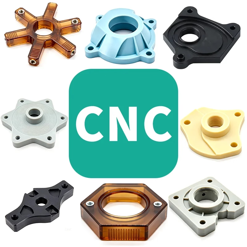
What SLC CNC machining actually does to a part
SLC stands for stereolithography, and in production shops the term is often used loosely for any resin-based layer process. A laser cures liquid photopolymer one layer at a time, usually between 0.05 mm and 0.1 mm per pass. The result is a solid part with fine surface detail and internal channels that a cutter cannot reach.
That printed part is not the finished part. It goes onto a CNC machine for the features that carry load, seal, or fit. Mating faces, bores, threads and datums get cut. The printer builds the geometry cheaply; the cutter sets the accuracy where it matters.
This split is the whole point. You are not choosing between printing and machining. You are choosing which features deserve metal removal and which can stay as cured resin. Get that assignment wrong and you pay for both processes without gaining anything.
The laser path also leaves a green part that needs washing and a final UV cure. Skip the cure and the part keeps shrinking for days after it leaves the machine, which shows up later as a bore that no longer fits its pin.
Where the tolerances really live
A printed layer is accurate to a few tenths of a millimeter at best. Resin shrinks as it cures, and the shrink is not uniform across a tall part. Walls thinner than about 0.5 mm tend to warp or sag before the cure is complete.
Machined features behave differently. On our 5-axis centers we hold ±0.005 mm (±0.0002 in) on critical dimensions and reach Ra 0.2–0.8 μm on a finished face. Those numbers apply to cut surfaces, not to the printed skin next to them.
So the drawing has to say which is which. If a callout of ±0.05 mm sits on a printed boss, no amount of finishing will rescue it. Move the tolerance to a machined face, or accept the looser number and design the joint around it.
Inspection follows the same logic. We check raw material, monitor in process, and inspect 100% before shipment, with reports on request. A first article report that lists printed and machined features separately is far easier to argue about than one flat number.
Geometry that suits the hybrid route
The process earns its place when a part has one or two tight interfaces and a lot of organic or internal shape around them. A manifold with curved internal channels and a flat sealing face is a textbook case. Print the channels, cut the face.
It also works for low-volume housings where tooling cost would dominate. From one prototype to 10,000+ part runs, we run no minimum order quantity, so a printed-and-finished housing can carry a product through early builds without a mold.
Thin ribs, deep pockets and undercuts are cheap to print and expensive to mill. That is exactly where the printer should do the work. Let it handle the features a 3-axis cutter would need three setups to reach.
Where it does not suit: parts under sustained load, high-temperature service, or any feature that must hold a thread under torque. Cured photopolymer creeps. A printed thread boss will strip long before a machined one does.
Material choice for printed and machined halves
The printed half is limited to photopolymer resins, and those resins differ mainly in stiffness, temperature resistance and clarity. None of them match aluminium or stainless for strength or thermal stability, so the material decision usually follows the load path.
The machined half can be almost anything in our stock: 6061-T6, 7075 and 2024 aluminium; 303, 304, 316L and 17-4PH stainless; 1018, 1045 and 4140 steel; C36000 brass; TC4 titanium; or engineering plastics such as POM, PEEK and PC.
A common hybrid is a printed duct or cover bonded to a machined aluminium flange. The flange carries the bolt load and the seal; the duct handles airflow. Both halves do what they are good at.
If the whole part must pass a temperature or load requirement, skip the resin entirely. A machined part from 7075 or 17-4PH will meet ±0.005 mm and hold its shape. A printed part will not, no matter how it is finished.
Choosing between SLC and straight CNC
Read down the column that matches your part.
| Part requirement | SLC plus CNC finishing | Straight CNC machining |
|---|---|---|
| Internal curved channels | Printed, no tool access needed | Needs split design or lost core |
| Sealing face flatness | Machined after printing | Machined in one setup |
| Tolerance on all features | ±0.005 mm only where cut | ±0.005 mm across the part |
| Load-bearing thread | Not recommended, resin creeps | Standard, holds torque |
| Service above 80 °C | Resin softens, avoid | Metal grades fine |
| Low-volume housing | No tooling cost | Higher setup per unit |
| Wall under 0.5 mm | Prints well, may warp | Thin walls deflect in cut |
| Surface finish range | Ra 0.8–1.6 μm on cut faces | Ra 0.2–0.8 μm achievable |
Pick the process by the load path, not the shape
If the part has one tight interface and a lot of internal or organic geometry, print the body and machine the interface. If load, heat or thread strength runs through the whole part, machine it from metal.
Common questions
Is SLC the same as SLA?
In practice, yes. Both refer to laser curing of liquid photopolymer layer by layer, and shops use the two terms for the same equipment. The difference that matters is not the name but what happens after printing, meaning whether the part goes onto a CNC machine for its critical features.
Can a printed part be tapped?
Yes, but the thread is only as strong as the cured resin. For anything that will be tightened more than once, we prefer to print an undersized boss and cut the thread in metal, or bond in a machined insert. We will flag this during DFM review if a printed thread appears on your drawing.
How do I dimension a hybrid part on the drawing?
Split the callouts. Put tight tolerances only on features you expect to be machined, and mark them as such. Leave printed features at a realistic printed tolerance, usually ±0.1 mm or looser. This avoids a drawing that no process can satisfy and shortens the quoting round.
What file formats do you need?
STEP is preferred for the machined geometry because it carries true surfaces. STL is acceptable for the printed body, though a finer mesh gives a better starting surface. Send both if the part is hybrid, and note in the file which faces are critical.
Does the resin absorb moisture?
Some resins do, and a damp printed part can change dimension slightly over weeks. For parts that sit in humid or wet service, we recommend a machined plastic such as POM or PEEK instead, or a sealed coating on the printed surface. Tell us the service environment at quote stage.
What lead time should I plan for?
Quotation and free DFM analysis come back within 12 hours, and production can start within 24 hours. Parts ship in 3–5 days. A hybrid part needs both a print run and a machining setup, so add a day or two to your own schedule rather than assuming a single-process timeline.
Send the drawing, get a process call
Upload your files and we will tell you which features should be printed, which should be cut, and what the part will actually hold.
12-hour quoteFree DFM analysis100% inspection
More from the shop floor
We publish setup notes, tooling trials and inspection data from the factory floor.











